
"what is the value of la?"
Over 6-7mA ... in the "wrong" part of anode curves.
This is what happens when copying values "automatically" from significantly different operating arrangement.
Over 6-7mA ... in the "wrong" part of anode curves.
This is what happens when copying values "automatically" from significantly different operating arrangement.
Well, it's your amp. You should now the tube anode current.
If you don't know that you can't calculate it.
Jan
If you don't know that you can't calculate it.
Jan
If I don't want to have a capacitor in series with the grid, can I battery bias (e.g. 4 x 1.5V alkaline) ?
With what do you want to drive the grid? Can that be done DC coupled? If not you need a cap.
Jan
Jan
Cathode biased stage doesn't require input capacitor. The grid voltage is 0V DC via grid leak resistor.If I don't want to have a capacitor in series with the grid, can I battery bias (e.g. 4 x 1.5V alkaline) ?
p.s. do you read this ?
Sorry if this is a dumb question. What is the watt rating of the 500R cathode resistor?
Should be a few milliAmps flowing through that resistor but lets allow a maximum of 20 milliAmps so Watts equals current squared times resistance, that's 200 milliWatts.
So a 250 milliwatt resistor would be fine but make it a Half Watt resistor just to be ultra stupid safe, so that's a 500 Ohm 0.5 Watt resistor from the Cathode to Common (Ground) as shown on the circuit diagram.
It's an interesting project getting such an old tube working again! Well done you for attempting it.
This tube is delicate, don't let the heater voltage get any more than 5 Volts AC.
The 100uF capacitor from the Cathode to Common (Ground) as shown on the circuit diagram, will make distortion but if you want even more distortion try increasing the value of the 500 Ohm resistor. Try 1000 Ohm or 2000 Ohm again all Half Watt 0.5 Watt resistors.
Increasing the value of that resistor makes the Anode to Cathode current Ip drop the lower the value of Ip the more nonlinear the amplification gets and nonlinearity creates tube distortion.
The 100K resistor from Grid to Common (Ground) can be 0.25 Watt resistor. Hope that helps.
Last edited:
Cathode biased stage doesn't require input capacitor. The grid voltage is 0V DC via grid leak resistor.
Yes it does need an input capacitor! It depends on where the input is coming from.
Some inputs may have a DC level on them so its wise to have an input capacitor. A DC level on the Grid will screw up the bias.
Another important reason for having an input capacitor is safety. Consider for example the tube fails and shorts the Grid to the Anode, now you have the full B+ HT on the Grid and therefore on the input wiring, with an input capacitor no problem without you can get a hell of a belt off the input wiring.
If you are 100% sure the signal you have as input has no DC level on it then fine you don't need the input capacitor. In any event its not going to do any harm staying where it is.
"Grid leak resistor" is a terrible jargon - the Grid has a leakage current which can be vanishingly small for negative Grid voltages and quite large for positive Grid voltages. Putting a 100K resistor between the Grid and Common (Ground) fixes the Grid leakage current.
Remember this tube is old and delicate.
Last edited:
If I don't want to have a capacitor in series with the grid, can I battery bias (e.g. 4 x 1.5V alkaline) ?
Don't even think of it! Leave the input capacitor there it should be a 2.2 uF 400 Volt film capacitor.
The Anode to Cathode current passing through the 500 Ohm resistor lifts the Cathode voltage above Common (Ground) and a balance is achieved depending on the tube characteristics. Lets say the tube doesn't want to carry much current when the Grid gets about 3.5 Volts negative (in reality of this circuit its the Cathode lifting positive of the Grid - same result) Now there is 3.5 Volts across the 500 Ohm resistor so the Anode to Cathode current Ia is 3.5/500 which is 7 milliAmps.
Last edited:
Thanks Rich and everybody.
Does the 01A tube have 'unique harmonic distortion characteristics' inside its classic linear zone, produced in part by AC filaments and choke/interstage loaded anode?
If so, will the unique harmonic distortion characteristics of the tube be the same type, when run outside it's linear zone?
What happens to the tubes unique harmonic distortion characteristics when a grid bias is applied (as oppose to a cathode bias)
🙏
Does the 01A tube have 'unique harmonic distortion characteristics' inside its classic linear zone, produced in part by AC filaments and choke/interstage loaded anode?
No idea, but you could try connecting an Inductor (Choke) between the B+ 120 VDC and the tube Anode. Normally the distortion tubes produce is harmonics. For example if you were getting a note from your bass guitar of 200Hz you would get harmonics at 400Hz, 600Hz, 800Hz etc. See this FFT plot from a distorting tube:
If so, will the unique harmonic distortion characteristics of the tube be the same type, when run outside it's linear zone?
No idea.
What happens to the tubes unique harmonic distortion characteristics when a grid bias is applied (as oppose to a cathode bias)
Electrically they are the same thing. What creates the distortion is high gain at low Anode to Cathode current.
By definition if the tube is operating linearly it will not distort the signal. That said Triodes cannot ever operate entirely linearly. Its possible to reduce distortion by using negative feedback. In this way a well designed Triode can show useful gain at a Total Harmonic Distortion level of better than -80dB.
-
By the way your original circuit could be made to work with some really big resistors that get hot.
Current flows through the 500R resistor, through the heater, through the 22R resistor, it biases the Cathode to 5 Volts positive, the current is about 230mA so shouldn't blow the heater but it probably will.
7 Henry is a massive Inductor don't know if its there just to protect the heater and take out mains hum or also to contribute to the distortion. Its possible that the thing will oscillate at low frequency, make the Heater flicker and create a weird sound??
Last edited:
Thanks again Rich.
From what I've read , I think I'm after predominantly third harmonics , but for sure, I'm definitely after a harmonic and compression structure that I enjoy. I will absolutely try choke loading the anode 👍
I wonder how the output load will change the distortion content..
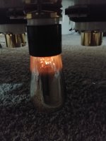
One thing for sure...they look pretty 😀
From what I've read , I think I'm after predominantly third harmonics , but for sure, I'm definitely after a harmonic and compression structure that I enjoy. I will absolutely try choke loading the anode 👍
I wonder how the output load will change the distortion content..
One thing for sure...they look pretty 😀
Attachments
If it is inside its linear zone, it is linear. Linear means no distortion.
Most designers try to run their tube (FET, transistor) in their linear working point, so they don't distort. Except for guitar amps.
Distortion is caused by non-linear characteristics.
If changing the load changes the distortion that is because with that load the tube is run in it's non-linear characteristics.
Jan
Last edited:
Did you know the 201 with the tungsten filament seems to last forever. 100 year old tubes tests as new. Two parallel each side for PPP 201 tubes would be killer on a Klipshorn Cornwall speaker. Likely make enough volume for average listening. I should build a 201 amp. What would a PPP 201 make in watts? .2 watts? A 71A or 112 tube is likely a better bet. May make 1 watt in PPP?
Last edited:
From what I've read , I think I'm after predominantly third harmonics , but for sure, I'm definitely after a harmonic and compression structure that I enjoy. I will absolutely try choke loading the anode 👍
Yes looking at the spectrum in post #32, the fundamental 1st harmonic is of course there at 200Hz, the 2nd harmonic at 300Hz is missing the 3rd harmonic is there at 400Hz etc.
At least its something like that you need to study it, all I know is that tube distortion is found to be a good sound by most people.
Its always like that with tubes, here is the harmonics shown as vibrating string:
Last edited:
The general concensus is that even order harmonics are experienced as 'nice' giving the sound a 'warm' character.
Odd orders are generally connected to shrill and harsh sounds. Most listeners like 2nd, 4th etc but abhor 3rd, 5th and 7th etc.
Jan
Odd orders are generally connected to shrill and harsh sounds. Most listeners like 2nd, 4th etc but abhor 3rd, 5th and 7th etc.
Jan
general concensus is that even order harmonics are experienced as 'nice' giving the sound a 'warm' character.
Odd orders are generally connected to shrill and harsh sounds. Most listeners like 2nd, 4th etc but abhor 3rd, 5th and 7th etc.
Yes makes sense, they are when a string vibrates there are even number of standing waves along it not odd.
The spectrum in post #32 I made from a distorting tube circuit with fundamental at 200Hz, there's no 300Hz, no 500Hz etc, the harmonics that show up are 400Hz 600Hz 800Hz 1000Hz.
You can easily vibrate a string at 3 x or 5 x etc of the fundamental, as shown in your above post.
The point is that even order is perceived as pleasant sounding, odd sounds unpleasant to most.
That's why many prefer single ended amps with their predominant even order distortion.
Jan
The point is that even order is perceived as pleasant sounding, odd sounds unpleasant to most.
That's why many prefer single ended amps with their predominant even order distortion.
Jan
- Home
- Amplifiers
- Tubes / Valves
- 01A Question