some code and two pics of my preamp
Hi Rick,
you can find some code attached in a .txt-file. It just the NJW control code.
No user interface or so because this is hardly related to my hardware.
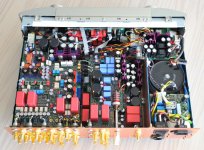
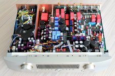
I will attach two photos of my self build preamp as well, where on can see
the tone control board. It is a little bit hiden behind the main board and the
active subwoofer crossover but i guess you will find it ;-).
Btw. i used a Marantz NR-1501 case for my amp from which i removed all
original electronics.
Hi Rick,
you can find some code attached in a .txt-file. It just the NJW control code.
No user interface or so because this is hardly related to my hardware.
I will attach two photos of my self build preamp as well, where on can see
the tone control board. It is a little bit hiden behind the main board and the
active subwoofer crossover but i guess you will find it ;-).
Btw. i used a Marantz NR-1501 case for my amp from which i removed all
original electronics.
Attachments
Hi Dirk,
Thanks, for the code sample, wow you have everything packed in there pretty tight.
Cheers
Rick
Thanks, for the code sample, wow you have everything packed in there pretty tight.
Cheers
Rick
elfenthau,
Your work looks beautiful. What functions and features have you built into it, and have you measured its performance parameters?
It has been some time since I posted here. After I created this thread, Boriss111 and I were discussing designing a low-noise preamp built around the NJW1119A chipset, and he was immediate in sourcing them from a distributor last winter. However, I fear something dire has happened. I have not seen him here since spring.
Very nice build out Elfenthau! I see lots of serious layout work and effort there. Congratulations!
Where did you get the case by the way?
(You can see my preamp with tone controls on my website - just follow the link below).
Where did you get the case by the way?
(You can see my preamp with tone controls on my website - just follow the link below).
Last edited:
@ Bonsai
Very nice and professional work! And may be not that far away from what i did.
I will attach two schematics (preamp + active crossover)
For the case i bought a used Marantz NR-1501. I took out all Marantz stuff
and build in my own ;-). The Marantz electronics i could sell for nearly the
some money i boght the device 🙂.
I am not a hifi purist, as you will see. I like comfort. So this somehow was a
major aim, at least getting most functions remote controlable.
Many ideas are mostly based on the books of Douglas Self.
The input stage consists of two parallel instrumentation amplifiers (less noise)
which can be bypassed via relays. The opamps are OPA827 for the first
and LME49720 for the second stage. This stage is low gain usually but can
be switched to +12dB if gain is required.
The input stage is followed by two (!) PGA2320 for each channel. The two
chips are put in parallel for lower noise and then followed by a crosscoupled
differential stage to lower 2nd harmonic distortion.
Behind the volume control there are relays enabling tone control and/or the
subwoofer crossover. Unfortunatelly crossover is no more differential any
more because of the excessive effort (space) for it.
Then a line driver = headphone driver follows made of OPA627 (not 827 as
in schematic) and a LME49600 buffer. This is bypassable via relays as well
for the line function. Headphone output will always have this driver active.
The PCB is a four layer one. I just reserved one layer for GND plane only.
Most signal lines (layer 2) are shielded between layer 1 and 3. All inverting
opamp inputs have a guard ring fed by its related output.
There is quite a nice feature with the electronic volume control. I programmed
my firmware so that i can set a level offset to each input, output and even
to compensate for tone control or crossover level uneveness. This offset
can be set in 0.5 dB steps. So this is a quite nice feature as it adjusts all
my input and output devices to a reasonable even level.
This should be enough for now. Have fun with the schematics. If you think
there are errors or imperfections do'nt hesitate discussing this. It is my
first audio project after 20 years ;-). It's probably not perfect!
Ah, ... i did not make any detailed measurements other the with frequency
generator and oscilloscope and of course hearing. We have a sprectrum
analyser in office but this starts at 10kHz which is not really usefull for audio.
Anyway i could make some comparison with and without input/output
stages just by bypassing them with the relays. I could not hear any differences
but this just may be a hint that i have no golden ears ;-).
Btw. i can also bypass the input and output capacitors which are WIMA
DC-Link polypropylene foil types.
Dirk
Attachments
Not able to find this chip.. Is there any new alternative for this?According to Mouser here in the US, the NJW1119 is obsolete and not available. Doubt you can buy it here in US.
Is it similar to NJW1194 available in mouser, from same manufacturer?
Can anyone tell me where to buy the NJW1119A in small quantities? I'm interested in starting a DIYproject based on it. Thanks! 🙂
Can anyone tell me where to buy the NJW1119A in small quantities? I'm interested in starting a DIYproject based on it. Thanks! 🙂
Answered here: https://www.diyaudio.com/forums/analog-line-level/342102-5-1-channel-preamp-3.html#post6120876
- Home
- Source & Line
- Analog Line Level
- 0.005% Distortion Tone Control Preamp, NJW1119A Chipset