We disclosed earlier our attempt in build the Kaneda No.168 Lineamp.
This has now been developed further to a full preamplifier to go with a Kaneda-type power amplifier.
The pdf attached describes the details of our implementation.

Patrick
.
This has now been developed further to a full preamplifier to go with a Kaneda-type power amplifier.
The pdf attached describes the details of our implementation.
Patrick
.
Attachments

The relay controlled resistor ladder attenuator is the same W-ONE as we used in the F5 Preamp.
One can purchase this at AliExpress, but not entirely without problems :
www.diyaudio.com/community/threads/help-with-w-one-ladder-relay-attenuator-remote-control.427834/
The standard W-ONE had shared common Gnd for left and right channels, 50k input resistance, and a large 3-digit 7-segment LED display.
We have replaced the two relay boards with our own 4-layer design to enable separate Gnd for each channel, as well as 10k resistance.
And the LED display board is resigned to suit the 3207 front panel.
In effect, we are only using the MCU board of the W-ONE.
But of course it is still 90% based on the original design concept.
Patrick
Beautiful, clean build and implementation! Well done once again and congratulations!
I'm looking forward to hearing from test listening sessions
For the low impedence load testing, would this be appropriate for headphones (with or without modification)?
Last question for now - any recommended substitutes for 2SC1400? BC550/54x?
Cheers,
Stephen
I'm looking forward to hearing from test listening sessions
For the low impedence load testing, would this be appropriate for headphones (with or without modification)?
Last question for now - any recommended substitutes for 2SC1400? BC550/54x?
Cheers,
Stephen
Firstly here are the relevant links :
https://www7b.biglobe.ne.jp/~konton/No-168 seisaku-4.htm
www.diyaudio.com/community/threads/any-suggestion-for-modification-of-hiraga-preamplifier-le-preamplificateur-kaneda.405466/post-7540216
The 2SC1400 in the first link is only used as a constant current source.
It is much simpler to use just one JFET plus a source resistor.
I used J113, but any Toshiba NJFET with sufficient Idss (>3mA) will also do nicely.
We have so many nice Class A headphone amps.
So this was not the intention.
It is more to be able to drive long cables for active speakers, for example.
Or perhaps some Class D amps.
Fran has actually already organised a listening session with friends this weekend.
This in combination with the GoFiSS.
An ABC test against a J2 clone being part of the program.
😊
Patrick
https://www7b.biglobe.ne.jp/~konton/No-168 seisaku-4.htm
www.diyaudio.com/community/threads/any-suggestion-for-modification-of-hiraga-preamplifier-le-preamplificateur-kaneda.405466/post-7540216
The 2SC1400 in the first link is only used as a constant current source.
It is much simpler to use just one JFET plus a source resistor.
I used J113, but any Toshiba NJFET with sufficient Idss (>3mA) will also do nicely.
For the low impedence load testing, would this be appropriate for headphones ?
We have so many nice Class A headphone amps.
So this was not the intention.
It is more to be able to drive long cables for active speakers, for example.
Or perhaps some Class D amps.
I'm looking forward to hearing from test listening sessions
Fran has actually already organised a listening session with friends this weekend.
This in combination with the GoFiSS.
An ABC test against a J2 clone being part of the program.
😊
Patrick
The original K168 circuit is the property of Mr. Kaneda.
We shall therefore make the Gerber files available to those interested to try out.
The BoM is set for a gain of 5 ( 10k : 2k ).
This is a simplified version of the PCB that we used.
And we have not tested this particular version, though it has been checked thoroughly.
So use at own risk.
In any case, I suggest you follow the schematics on the PCB to familiarise yourself with the layout before soldering.
We could make the Toshiba JFETs available, should you have difficulties sourcing them.
Patrick
.
Attachments
A word of warning.
Please note carefully pinout of the output devices on the PCB.
TO126 devices have reversed pinout than TO220.
Patrick
Please note carefully pinout of the output devices on the PCB.
TO126 devices have reversed pinout than TO220.
Patrick
Nice!We disclosed earlier our attempt in build the Kaneda No.168 Lineamp.
This has now been developed further to a full preamplifier to go with a Kaneda-type power amplifier.
The pdf attached describes the details of our implementation.
View attachment 1474370
Patrick
.
I think I have spotted an error in your schematic.
In the output you have 47 Ohm resistors.
I think this should be 0.47 Ohm.
I setup and got THD 0.00024% at 1kHz 1 Vrms into 10k.
Here is the schematic I used:

In the output you have 47 Ohm resistors.
I think this should be 0.47 Ohm.
I setup and got THD 0.00024% at 1kHz 1 Vrms into 10k.
Here is the schematic I used:
I think I have spotted an error in your schematic.
In the output you have 47 Ohm resistors.
I think this should be 0.47 Ohm.
No sir.
Not in my Spice model, AND also not in my actual build.
The actual build use 2x 91R in parallel, i.e. 45.5R.
All the distortion plots are also real measurements, not simulations.
Patrick
Someone else was interested in the case we use.
We ordered them from the OEM, but this is their international shop, as far as I can tell :
https://www.brz-hifi-audio.com/prod...ll-aluminum-preamplifier-chassis-hifi-diy-box
We asked for the rear panel without cutouts, as we don't use IEC sockets.
There is a deeper version (308mm instead of 248mm) at practically same price :
https://www.brz-hifi-audio.com/prod...aluminum-amp-box-can-install-goldmund-circuit
Patrick
I have been asked about the JFETs by PM.
We shall offer them curve tracer matched at working conditions, to enable you to build 2 channels.
The TTC004B and J113 are currently available and can easily be obtained from Mouser, etc.
But please wait until Fran has finished the audition this weekend.
Thank you for your interest
Patrick
We shall offer them curve tracer matched at working conditions, to enable you to build 2 channels.
The TTC004B and J113 are currently available and can easily be obtained from Mouser, etc.
But please wait until Fran has finished the audition this weekend.
Thank you for your interest
Patrick
These days, you can take a photo of a page, and get internet to translate to English for you.
🙂
Patrick
🙂
Patrick
Apparently the book is available at both Amazon UK and DE, but not US.
Seller is in Japan.
Maybe problems with tariffs to the States ?
Patrick
Seller is in Japan.
Maybe problems with tariffs to the States ?
Patrick

Member
Joined 2006
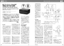
Just had a thought to share this information. 🙂 This is the latest issue of the MJ magazine, Spring 2025, in which one can find the Kaneda No. 297 DC hybrid IVC (amplifier) circuit within. Yes it's now advanced to No. 297! (IVC stands for IV Converter)
Input is a differential pair using WE396A, and the output devices are the latest 4th generation SiC mosfets by Rohm, SCT4013DR, and this 62W at 8 ohm IVC is powered by LiPo batteries, +- 48V for driver stage and +- 32V for the output SiC Mosfets.
Attachments
Last edited:
This is the latest issue of the MJ magazine, Spring 2025, in which one can find the Kaneda No. 297 DC hybrid IVC (amplifier) circuit within. Yes it's now advanced to No. 297!
If this is a power amp, perhaps more relevant at this thread ?
www.diyaudio.com/community/threads/semisouth-goes-dodo-what-now.222098/post-7281961
The SCT4013 is not really different to the other Rohm SiC MOSFETs in that the transconductance at ~1A is very low. It also requires a high Vgs.
So rather different to the Semisouth.
Was already discussed at the link above.
Unless of course you believe in Magic with SiC.
Maybe also GaN or Germanium ? 😊
www.ti.com/technologies/gallium-nitride.html
Cheers,
Patrick
For 15mA across the output stage and 47ohm there need to be ~1.32V across each 1k6 resistor.No sir.
Not in my Spice model, AND also not in my actual build.
The actual build use 2x 91R in parallel, i.e. 45.5R.
All the distortion plots are also real measurements, not simulations.
Patrick
This is not possible to create with only 0.4mA.
I get it the 1k6 resistor should be like 3k83 ...
Last edited:
The second stage bias is not 0.4mA.
All the information one needs to build the real thing is in the BoM, and of course the Gerber.
I know what I have built.
And I know what DC currents I have, in real.
Cheers,
Patrick
All the information one needs to build the real thing is in the BoM, and of course the Gerber.
I know what I have built.
And I know what DC currents I have, in real.
Cheers,
Patrick
Last edited:
- Home
- Source & Line
- Analog Line Level
- The Kaneda No.168 Preamp