Few weeks ago I encountered a Sonab speaker (I think it was a OA5) fitted with a Philips M9710 driver, the back of the driver covered with a basked lined with damping material.


 Photos from Troels Gravensen website here.
Troels descibes the purpose of this construction.


To keep it simple I just covered the back of the driver with gaffa tape.


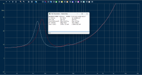
And measured again the TS parameters and impedance. Red is driver impedance, White driver impedance with added mass (7 gram)


Effects:
I repeated the experiment with masking tape instead of gaffa tape. The result was essentially the same. To illustrate the effect of these changes I simulated a closed box with Basta:

Box 2ltr
GHP C=1200uF
Viso=80%
Qb=20
driver no tape Fs (-3dB) = 103Hz, Eff 81,2dB
driver with tape Fs (-3dB0 = 80Hz, Eff. 80,3dB
So for a loss in efficiency of about 1dB we can lower the Fc of the speaker from 103Hz --> 80Hz. The effect seems to be caused by the added mass due to the air enclosed between the cone and tape, and the added resistance to the air moving.
The method used by Sonab seems to be a way to control the effect.
Troels descibes the purpose of this construction.
I remember having seen similar constructions in fifties and sixties radio's. Seeing it again made me curious, so I did a small experiment using a pair of mini 3 inch woofers (originally from a pair of Peaq PC speakers). I measured the TS parameters, shown right.the 9710 driver placed in a metal mesh basket with some heavy glassfiber material between driver and mesh, making a low-pass filter that can be adjusted due to the basket being suspended on three screws that allows you to increase or decrease the acoustic resistance of the fiber material. An acoustic vent, sort of. Something similar can be found on some Lowther drivers.
To keep it simple I just covered the back of the driver with gaffa tape.
And measured again the TS parameters and impedance. Red is driver impedance, White driver impedance with added mass (7 gram)
Effects:
| Parameter | No damping | With damping |
| Fs | 91,5 | 83,5 |
| Qms | 4,18 | 3,11 |
| Qes | 1,0 | 0,87 |
| Qts | 0,72 | 0,76 |
| Cms | 0,383 | 0,333 |
| Rms | 1,09 | 1,84 |
| Bl | 6,24 | 6,55 |
| dBspl | 81,4 | 79,0 |
| Vas | 0,99 | 0,86 |
| Mms | 7,9 | 10,9 |
I repeated the experiment with masking tape instead of gaffa tape. The result was essentially the same. To illustrate the effect of these changes I simulated a closed box with Basta:
Box 2ltr
GHP C=1200uF
Viso=80%
Qb=20
driver no tape Fs (-3dB) = 103Hz, Eff 81,2dB
driver with tape Fs (-3dB0 = 80Hz, Eff. 80,3dB
So for a loss in efficiency of about 1dB we can lower the Fc of the speaker from 103Hz --> 80Hz. The effect seems to be caused by the added mass due to the air enclosed between the cone and tape, and the added resistance to the air moving.
The method used by Sonab seems to be a way to control the effect.
Attachments

This is not the expected behaviour. Was this observed, or perhaps just speculation?making a low-pass filter that can be adjusted due to the basket being suspended on three screws that allows you to increase or decrease the acoustic resistance of the fiber material.
Pure nonsense, these are old dust covers.
The cloth on the back of the speaker is = absorption material
Being directly on the back of the driver is similar to lining a cabinet with absorption material.
Pressure needs to pass through it.
Troels is also full of crap.
Older speakers used these dust covers, the added benefit was slight absorption directly on the back of the cone.
Duct tape or masking tape is creating a leaky enclosure.
The impedance curve would be completely opposite.
Fs will raise in a enclosure.
They look cool I think, keeps dust and debris out of coil for old open back radio speakers.
Many or most were still electro magnets/ field coil with bucking coils.
Something open baffle heads could use to look interesting and offer very very slight absorption
Last edited:
You just overcomplicated it. Cover must be breathable - no gaffa or masking tape! Try with thin felt.To keep it simple I just covered the back of the driver with gaffa tape.
If it is a thin fabric, it is dust cover only. If it is a thicker felt, it will change somewhat Thiele-Small parameters of the driver.
If I don´t remember wrong, the basket was just to protect the driver from the damping material. And the purpuse of the damping material around the basket was to lower the Qts to better fit with the BR alignment.
I have no data to confirm that. This is an old construction, but also the most popular loudspeaker ever in Sweden.
I have no data to confirm that. This is an old construction, but also the most popular loudspeaker ever in Sweden.
Regarding the damping and mesh on the back of the driver:
If it moves with the driver, it increases Mms and lowers Fs a bit
If it increases flow resistance it increases Rms and reduces Qms
The desired effect is a lowering of Qts. If you have a driver with a Qes of 0.8 and a Qms of 5 (Qts~0.7) and you can reduce the Qms to 1 (Qts~0.4) you have expanded the driver's utility a lot.
Generally it will be a combination of things because it would have to be stretched awful tight not to move with the driver. I think some car audio nuts were using nonwoven scrim (something like on the bottom of furniture) stapled tightly to the back of drivers and calling it an "Aperiodic membrane" or something like that.
It's also an old-school reflex-box damping tool that appears in those articles at least by the '40's. As above, it it moves, it's a little of an inertance.
At least regarding the reflex application, the argument goes: if you apply resistive materials to a port only, you damp one thing. If you apply it to the back of the driver, you damp two things.
For the specific/subject loudspeaker case, no exp.
At least regarding the reflex application, the argument goes: if you apply resistive materials to a port only, you damp one thing. If you apply it to the back of the driver, you damp two things.
For the specific/subject loudspeaker case, no exp.
Regarding that difference between box mode damping and fundamental damping.
This caged resistive element will damp the driver Qms, so affects the fundamental reflex enclosure resonance. Obviously this is wanted to achieve a bass alignment.
Box mode stuffing usually tries to avoid affecting that resonance. Lining close to the walls deals with the highs without much effect on the lows. The designer could work out where to draw the line on the spectrum and pull the lining away from the walls by just that amount to improve the reduction of unwanted box modes.
In such a case the fundamental resonance is going to be touched slightly, it's reduction should be incorporated into the design hence the ability to use the parameter of QLoss with box calculators.
I agree, these are the two effects you can expect to happen.Regarding the damping and mesh on the back of the driver:
If it moves with the driver, it increases Mms and lowers Fs a bit
If it increases flow resistance it increases Rms and reduces Qms
The desired effect is a lowering of Qts. If you have a driver with a Qes of 0.8 and a Qms of 5 (Qts~0.7) and you can reduce the Qms to 1 (Qts~0.4) you have expanded the driver's utility a lot.
Generally it will be a combination of things because it would have to be stretched awful tight not to move with the driver. I think some car audio nuts were using nonwoven scrim (something like on the bottom of furniture) stapled tightly to the back of drivers and calling it an "Aperiodic membrane" or something like that.
I did some searches for other references.
I found an old reference in
G. Slot: "Van Microfoon tot Oor", Philips Technische Bibliotheek 1955-1960 [From microfphone to ear, Philips Technical Library 1955-1960], Pg.106
https://www.diyaudio.com/community/threads/enclosure-for-high-q-driver.83982/page-2
This is a good axample of the effect of an increased flow resistenace.
Another reference is quoted here.
I could not find the original document quoted, there is not enough information for that.
Small : Chapter 6. DRIVER DAMPING AND VARIATIONS OF THE CLOSED-BOX SYSTEM
"6.2. Acoustic Damping of the Driver
The simplest way to correct a high value of QTS is to apply acoustic damping directly to the driver using a shroud of acoustically resistive material as described in [G1] or [N3]. This effectively adds resistance in series with RAS and leads to a value of QM ( Section 1.5.4 ) lower than QMS. By suitable choice of the kind and amount of damping material, almost any desired value of QT can be obtained regardless of the value of QES or QE. The parameter measurement methods of Section 9.2 may be used to determine experimentally the amount of material needed to meet a particular requirement. Care must be taken that the material remains stationary."
Protection of the driver was an issue for very old drivers (20's, 30's I think) where there was the risk of dust (and damping material) entering the air gap and obstructing the voicecoil movement. Later drivers have no exposed air gap, and don't need this kind of protection. including the Philips 9710M.If I don´t remember wrong, the basket was just to protect the driver from the damping material. And the purpuse of the damping material around the basket was to lower the Qts to better fit with the BR alignment.
I have no data to confirm that. This is an old construction, but also the most popular loudspeaker ever in Sweden.
And I agree that the intention of the construction was to improve the bassreflex alignment.
Attachments
Some emore measurements with the Tectonic TEBM65C20F-8 driver.


Impedance and TS parameters (white=with added mass 7 gr)

Driver with 2mm felt damping


Impedance and TS parameters (white=with added mass 7 gr)

Driver with Gaffa tape damping

Impedance and TS parameters (white=with added mass 7 gr)

Driver with Masking tape damping


Impedance and TS parameters (white=with added mass 7 gr)

Driver with eggcrate foam damping


Impedance and TS parameters (white=with added mass 7 gr)

Combined impedance curves:

Red=driver no damping White=2mm felt Green=Gaffa tape Yellow=Masking tape
The eggcrate foam file is misplaced somewhere, I will add that when I find it.
TS parameters (Sd=37,2cm²)
Impedance and TS parameters (white=with added mass 7 gr)
Driver with 2mm felt damping
Impedance and TS parameters (white=with added mass 7 gr)
Driver with Gaffa tape damping
Impedance and TS parameters (white=with added mass 7 gr)
Driver with Masking tape damping
Impedance and TS parameters (white=with added mass 7 gr)
Driver with eggcrate foam damping
Impedance and TS parameters (white=with added mass 7 gr)
Combined impedance curves:
Red=driver no damping White=2mm felt Green=Gaffa tape Yellow=Masking tape
The eggcrate foam file is misplaced somewhere, I will add that when I find it.
TS parameters (Sd=37,2cm²)
| Parameter | Driver no damping | 2mm Felt | Masking tape | Gaffa tape | Eggcrate foam |
| Fs | 124,5 | 124,5 | 107,7 | 107,7 | 125,2 |
| Re | 7,0 | 7,1 | 7,1 | 7,1 | 7,1 |
| Qms | 5,33 | 4,18 | 3,21 | 2,66 | 4,86 |
| Qes | 1,64 | 1,7 | 2,25 | 2,02 | 1,7 |
| Qts | 1,26 | 1,21 | 1,32 | 1,15 | 1,26 |
| Cms | 0.26 | 0,26 | 0,27 | 0,27 | 0,26 |
| Mms | 6,3 | 6,3 | 8,2 | 8,2 | 6,16 |
| Rms | 0,92 | 1,18 | 1,73 | 2,09 | 1,0 |
| Bl | 4,58 | 4,54 | 4,19 | 4,42 | 4,50 |
| dBspl | 79,7 | 79,6 | 76.6 | 77,04 | 79,7 |
| Vas | 0,5 | 0,5 | 0,51 | 0,51 | 0,51 |
Though the tape increases Mms and lowers Fs at small signal levels, the small enclosed area will restrict excursion and flap at higher drive levels.TS parameters (Sd=37,2cm²)
- Home
- Loudspeakers
- Subwoofers
- Effect of damping on the back of a woofer