Hi everyone,
I am hoping to implement one of the solutions presented on this thread :
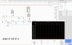
I have entered the first circuit into EasyEDA (standard Windows install version 5.4.46) because I have all the parts already.
In the second photo from the thread we see the simulation working as desired, with 3.6V for one second and then dropping, however, in my EasyEDA, the simulation does not turn on the LED and the voltage at output is 0.6V.
Can anyone see the problem? What must I add to for it work?
I tried adding a 1M resistor in parallel with C1, and then the LED does light up and we have 1.86V on the output, but it never drops.
Thank you for any help.
EJ
I am hoping to implement one of the solutions presented on this thread :
Hi all,
I am currently working on implementing LM1876 based amp and ran into the issue with the mute and standby pins.
From the datasheet, if a logic high (1.5 to 5V) is applied to the MUTE pin, the amp will be muted.
The goal is to mute the amp during the turn on (and turn off).
For that a logic high needs to be applied to the MUTE pin when amp is turned on, but after 1 or 2 seconds wait time the MUTE pin should be pulled low (< 1.5V).
I have come up with a simple simulation circuit that consists of :
Power is taken...
I am currently working on implementing LM1876 based amp and ran into the issue with the mute and standby pins.
From the datasheet, if a logic high (1.5 to 5V) is applied to the MUTE pin, the amp will be muted.
The goal is to mute the amp during the turn on (and turn off).
For that a logic high needs to be applied to the MUTE pin when amp is turned on, but after 1 or 2 seconds wait time the MUTE pin should be pulled low (< 1.5V).
I have come up with a simple simulation circuit that consists of :
- 5V zener regulator
- RC time delay
- NOT logic gate
Power is taken...
I have entered the first circuit into EasyEDA (standard Windows install version 5.4.46) because I have all the parts already.
In the second photo from the thread we see the simulation working as desired, with 3.6V for one second and then dropping, however, in my EasyEDA, the simulation does not turn on the LED and the voltage at output is 0.6V.
Can anyone see the problem? What must I add to for it work?
I tried adding a 1M resistor in parallel with C1, and then the LED does light up and we have 1.86V on the output, but it never drops.
Thank you for any help.
EJ
Attachments
I have recently been working at TI amp in the TPA31XX range. They also use a logic low MUTE function. I have implemented, simulated, and tested on a PCB the following mute circuit that seems to work.
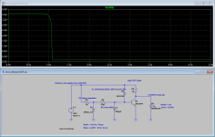
My design was a based on a 24V supply (not the 25V you show) and I was driving for around 2s to reach a 2V logic level. You can play with the resistors and capacitor values to get to where you want for your 1.5V. This design shows about 2.5 seconds to reach 1.5V at 25V supply. This one wont help with power off, but making a circuit to do both would be much more involved.
I simulated this originally in TINA-TI (free), but the curve here is from CircuitLab as I'm at work and don't have TINA handy. I find TINA, despite it's super clunky interface, to be super fast and reliable. Give PSPICE for TI a pass. Somewhat nicer interface, but slower than two weeks full of Christmases and is difficult to use.
I also have recently design and simulated an audio signal detect circuit using a LM393 comparator that will unmute only when an audio signal > 100mV is detected and remute after 5s of no audio. It also does power on pop control, but ONLY if you don't have active audio when you power it on. Let me know if you want me to share that one as well.
clunky to actually use.
Hey thanks ! I'll test it out as soon as can, probably Friday.
The LM1876 is MUTED at above 2.5V, so this looks close as it.
The LM1876 is MUTED at above 2.5V, so this looks close as it.
I actually like the circuit you linked. I’d need to calculate the power loss for the zener regulator to see how much I like it.
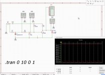
I’m wondering if the EasyEDA simulator is working correctly. The original poster used TINA-TI which is free via TI. Try simulating in that program. The only item you MAY have to add is the 5V zener diode, but there’s lots of examples online of how to add the spice models to TINA. I’ll see if I can make it this evening as I like this circuit as well.
I’m wondering if the EasyEDA simulator is working correctly. The original poster used TINA-TI which is free via TI. Try simulating in that program. The only item you MAY have to add is the 5V zener diode, but there’s lots of examples online of how to add the spice models to TINA. I’ll see if I can make it this evening as I like this circuit as well.
I didn't have time to model this up last night, but I did some calculations and I think that 30K resistor is too large. For a collector current of 25mA, you'll need more base current to turn on the BJT. Lower that resistor to 16kohm and see what happens in your EasyEDA simulation. Again, it'll depend on how accurately the simulator is modeling the BJT, but my review of the datasheet (and a refresher on my BJT basics from 20+ years ago in school) show you need more Ib.
Make sure to start the power supply at 0 V when you run the simulation. You want a circuit that tracks the power supply on startup and then snaps to 0 V after some delay.
Although the mute and standby inputs appear to be designed for use with 5 V logic, I don't see anything in the data sheet that would indicate that 5 V is the maximum that can be applied to those pins. So I don't think you need to clamp the mute or standby pin levels. Also... Using an LED as a clamp is not the hottest idea as the forward voltage of the LED is typically not a tightly controlled parameter. It's better to use a zener diode for this - if a clamp is needed, that is.
Looking at the equivalent schematic for the LM1876 (below), I'm thinking that a simple parallel RC combination would work. The C in combination with the CCS in the mute circuit sets the time constant on power-up. The R in parallel with the C discharges C when the power is turned off. One could use a diode in series with R to speed up the discharge if needed.
The only unknown variable is the current in the CCS, which is not specified. You could measure this pretty easily. Well... Easily if you have an ammeter that can measure µA. If not, hook 10-100 kΩ from the mute pin to VCC and measure the voltage drop. Calculate the current from Ohm's Law. Then use C = Q/V <=> C = I*t/V to find C. I is the current of the CCS. V is the voltage across the capacitor that's needed to un-mute the chip (so VCC-0.8) and t is the delay time from startup to un-mute.

Tom
Although the mute and standby inputs appear to be designed for use with 5 V logic, I don't see anything in the data sheet that would indicate that 5 V is the maximum that can be applied to those pins. So I don't think you need to clamp the mute or standby pin levels. Also... Using an LED as a clamp is not the hottest idea as the forward voltage of the LED is typically not a tightly controlled parameter. It's better to use a zener diode for this - if a clamp is needed, that is.
Looking at the equivalent schematic for the LM1876 (below), I'm thinking that a simple parallel RC combination would work. The C in combination with the CCS in the mute circuit sets the time constant on power-up. The R in parallel with the C discharges C when the power is turned off. One could use a diode in series with R to speed up the discharge if needed.
The only unknown variable is the current in the CCS, which is not specified. You could measure this pretty easily. Well... Easily if you have an ammeter that can measure µA. If not, hook 10-100 kΩ from the mute pin to VCC and measure the voltage drop. Calculate the current from Ohm's Law. Then use C = Q/V <=> C = I*t/V to find C. I is the current of the CCS. V is the voltage across the capacitor that's needed to un-mute the chip (so VCC-0.8) and t is the delay time from startup to un-mute.
Tom
That doesn’t make sense. I don’t trust that simulator.
I will say that I don’t think that circuit adds any value over the more simple circuit. I don’t think it actually mutes before power down like he believed it did anyway because the BJT stays biased too long.
I got my mute circuit from here. TPA AMPMute circuits
See the Giancarlo circuit.
I will say that I don’t think that circuit adds any value over the more simple circuit. I don’t think it actually mutes before power down like he believed it did anyway because the BJT stays biased too long.
I got my mute circuit from here. TPA AMPMute circuits
See the Giancarlo circuit.
Thank you Tom and BOC for the input.
I breadboarded the circuit too, and get the same (none) results on the scope. Had a long day at work today so I didn't have a moment to try anything else today, but tomorrow I will try out the TPA mute circuit on the simulator, and try the resistor change on the breadboard.
About the LED, one of the draw backs is in the EasyEDA simulator, the oscilloscope does not work. So I will implement a zener on the output and try it out too.
Cheers all
EJ
- Home
- Amplifiers
- Chip Amps
- Mute circuit for LM1876