Hello,
I got an Akai AM2450. I am trying to understand a bit of the schematics. (here joined)
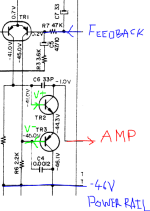
Here the input of the amplifier stage. The differential pair takes its input from the pre-amp.
At the output of the differential pair, V+ is connected to the base of a PNP, and V- to the base of the NPN.
I am wondering what is this schematics doing ? In particular, they give voltage when no inputs, and I see 2.3V between the NPN base and emitter, which surprises me (0.7V would no be a maximum before failure ?)
Thanks !
I got an Akai AM2450. I am trying to understand a bit of the schematics. (here joined)
Here the input of the amplifier stage. The differential pair takes its input from the pre-amp.
At the output of the differential pair, V+ is connected to the base of a PNP, and V- to the base of the NPN.
I am wondering what is this schematics doing ? In particular, they give voltage when no inputs, and I see 2.3V between the NPN base and emitter, which surprises me (0.7V would no be a maximum before failure ?)
Thanks !
Attachments
Hi degleve,
IMO, the NPN/PNP pair you're asking about is just another differential pair. It's clever in that it avoids the parts needed to implement a current source to drive the emitters of TR2 and TR3, and operates near the negative rail without needing voltage "head-room."
I believe the voltages noted in the manual are mistakes. I predict if you measure actual voltages you'll find about 0.6V Vbe in both devices, just as you expect. Be careful with measuring techniques to avoid damage.
Cheers!
Last edited:


That's correct, but I would have said it passes the voltages on the collectors of TR1. It also serves at the so-called VAS (Voltage Amplification Stage).
Also note that R4 is about twice the value of R3. This is consistent with equal Vbe on both TR2 and TR3, and makes the bias currents in the both TR1 transistors roughly equal--- good for linearity, etc.
Also note that R4 is about twice the value of R3. This is consistent with equal Vbe on both TR2 and TR3, and makes the bias currents in the both TR1 transistors roughly equal--- good for linearity, etc.
Last edited:
The input stages consist of two NPN differential amplifiers in cascade.
But in the second DA, one of the transistors is changed to a PNP type, and its collector is connected to -V instead of +V.
Since those two transistors still conduct the same (and equal) current, the current source is not needed.
But in the second DA, one of the transistors is changed to a PNP type, and its collector is connected to -V instead of +V.
Since those two transistors still conduct the same (and equal) current, the current source is not needed.
This allow to use the differential s second output to also drive the VAS, this increase the OLG by 6dB
and hence reduce THD by 6dB compared to the usual single transistor VAS.
and hence reduce THD by 6dB compared to the usual single transistor VAS.
- Home
- Amplifiers
- Solid State
- What is this amp stage doing !? Akai AM2450