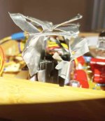
I got a preamp board and it works fine, but this one component (what exactly is it?), which is attached to a heat sink, gets very hot, while the other doesn't. Is this normal for this kind of device or should it be cooler? Pic attached. Thanks for any answers!
Attachments
Put a scheme if you havePic attached.
It is for filaments
The other maybe for HT
Walter
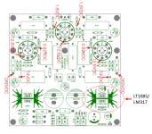
The LT1085/LM317 device is a low voltage regulator probably being used for the tube filaments. Probably at about 450mA total load. The K2700 is a high voltage chopper running a handful of milliamps. Depending on the actual AC filament input you are probably dissipating A LOT more power in the filament regulator than you are in the HV regulator. More dissipation means more heat.
You also need to define "very hot". What's the surface temperature of the heatsink? Anything under about 80°C (176°F) is probably fine. You could actually measure the voltages and perform the thermal calculations if you're worried about it.
You also need to define "very hot". What's the surface temperature of the heatsink? Anything under about 80°C (176°F) is probably fine. You could actually measure the voltages and perform the thermal calculations if you're worried about it.
Thanks for the answers. By "too hot" I mean too hot to keep my finger on the heat sink for more than a few seconds immediately after I shut off the power.... I don't have anything to measure the actual heat. The two heat sinks are the same size and type, which is why I suppose I question the heat at all.
The more current a regulator needs to deliver + how higher the difference between input and output voltage the higher the loss of power to heat.
You should measure for exact calculations.
You should measure for exact calculations.
Like Walter wrote: Please publish the schematic diagram,Put a scheme if you have
It is for filaments
The other maybe for HT
Walter
and then we can advice at which points of that diagram we want to measure by you the voltages/currents.
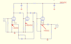
O.K. But can you please publish the schematic diagram from the filament supply part. The LT1085/LM317 part of that pcb?
The PCB silkscreen shows what looks like 12V input to a bridge rectifier. The LM317 is configured for 12.5 volts. The input to the voltage regulator is probably around 15V. Three 12AX7s at 12V, 150mA each, adds up to about 0.5A. So the power dissipated by the LM317 is approximately 3V x 0.5A = 1.5 watts. With a heatsink, its temperature should be acceptable.
Also, if you can touch the device for a few seconds with your finger, it's not too bad.
From Nelson Pass:
Blimey hot is 10 seconds hands on = 45 deg C.
Crikey hot is 5 seconds = 50 deg C.
Bloody hot is 2 seconds = 55 deg C.
X*?@! is 60 deg C.
Also, if you can touch the device for a few seconds with your finger, it's not too bad.
From Nelson Pass:
Blimey hot is 10 seconds hands on = 45 deg C.
Crikey hot is 5 seconds = 50 deg C.
Bloody hot is 2 seconds = 55 deg C.
X*?@! is 60 deg C.
If pinholer's numbers are correct, should be no more than Blimey hot. 1.5W should not be that much for what looks to be a decent heatsink. Very basic heatsinks for TO220 are 25C/W and I'd guess yours is more like 15. So 1.5x15=22C rise and ambient is usually are 25C so 47C. Take a look at either digikey or mouser and look for something that looks like yours to get a guess of the thermal resistance of a sink like yours.
You could consider to replace the heatsink for one with the exact same shape/format but in a longer version if you want it to be less hot.
You could also measure the input voltage to that regulator. Often tube designs use way too high voltages which gets burned to useless heat.
For educational purpose let's assume they used a 15V winding, that would be about 20..21V rectified/filtered DC. Simplified that would then be about 4W lost to heat. Now let's assume they used a 12.6V winding so 16..17V rectified/filtered DC voltage. That would be about 2.6W lost to heat. Just some examples what difference the input voltage causes. Also an LM317 needs 2V higher input than output voltage and a LT1085 only 1.3V (to function correctly).
Last edited:
Until your skin not remain on heatsink, stay safe!!!Those are the only graphical things I have for the layout.
Walter
That was always my understanding with the finger sensors.
about 60C being the pain threshold of instant ouch!! and not be able to hold it.
Keeping in mind the actual die temp of the semiconductor is hotter than the heatsink.
Generic assumption is 20 to 30C hotter? without exact calculation
about 60C being the pain threshold of instant ouch!! and not be able to hold it.
Keeping in mind the actual die temp of the semiconductor is hotter than the heatsink.
Generic assumption is 20 to 30C hotter? without exact calculation
Most spec sheets provide the dumb'ed down thermo analysis for electrical types. IE thermal resistors. A pretty typical theta-jc for a TO-220 pkg is 4C/W or a 4 degree rise at the junction to the case(Junction/Case, jc) per watt consumed. So in the above case if we are correct with our 1.5W consumption, about 6C hotter at the junction than the case. Similarly for us EE dummies, heatsinks offer the same model, theta-ca, thermal resistance from heat sink case to ambient, still air and often larger sinks are spec'ed with certain air flows. You just add up the theta-jc + theta-ca to get the total resistance like series resistors. There is also usually a tiny amount of thermal resistance with the thermal pad or insulator, although usually small enough to ignore. Pretty simple really assuming you know the power consumption. And never forget, this is to ambient. So if your sink is inside a sealed hot box, its the temp inside the box.
- Home
- Amplifiers
- Tubes / Valves
- Preamp LT1085/LM317 heat question