Over the past few months I have been sorting out my measurement techniques using the loopback scheme and have built a REW impedance rig.
Apologies this may be a long post.
Drivers - SB WO24P-4 woofer, Morel EM1308 Dome Mid, Morel ET448 Tweeter.
Box - Approx 40L sealed and medium stuffed with polyester toy stuffing. (re-purposed Akai SW125 box)
I finally got round to making a set of measurement the other day and have tweaked my active crossover to a point where I like the sound and theoretically it models well. The caveat here is that the room I have done the measurements in is not very large and has furniture in so quite a few reflections sothey are not perfect and have been smoothed. Measurement were taken at 1m at tweeter height and around 85dB loudness (roughly calibrated against mobile phone dB meter).
I took measurement from -90 to +90 degs for each of the drivers without moving the mic (note the Tweeter and Mid are both domes and so have protection capacitors, measurements taken with and with out these in place). I took nearfield for the woofer 1cm from the centre dust cap (sealed enclosure) and then impedance of each of the drivers in the box (with and without protection caps just for interest).

The results for the woofer seemed to suggest I am on the right track. The nearfield looks to be close to a Max Flat alignment which is what I was after. The 1m measurement aligns Ok with the manufacturer data and shows the baffle step below around 350hz (360mm wide baffle). Also the Impedance curve matches the Winisd output almost identically (peak : 32ohms at 47hz). So the box look pretty good for the WO24P-4 woofer.

I have been running a Minidsp Nanodigi crossover for a while and have had great fun playing with different slope filters and arrangements and also comparing it to crossover designs in VituixCad that seem to align quite well.
A quick check on the step/impulse response delays between the tweeter and the mid./woofer seem plausible at approx 5mm for tweeter to mid and 75mm for tweeter to woofer. So reference feedback seems to be working and has now embedded the acoustic offset into the phase measurements.
I then loaded up the +cap tweeter/mid and woofer measurements into VituixCad and played around with a few different designs with different slopes for an active crossover, these ranged from BW6 to LR24 in various combinations. The aim was to get a fairly flat on axis frequency response, align phase of each driver as close as I could (min 1 octave either side of the crossover point) and then have an in-room response that tried to follow a slope of 0.9dB/octave (or 6dB form 100hz to 10khz). Note, I did not merge the nearfield so it has room bass reflections under around 300hz.
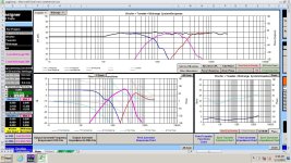
Without documenting all of the various trials and errors, I settled on the following scheme that seems to meet most of the requirements quite well. To me this sounded the best subjectively, it has a fairly large soundstage with decent separation between the instruments and has a natural and lifelike presentation. I could stand the vocals being a little more forward but this is the only minor criticism. Bass is plentiful in my 10ft x 10ft x 8.5ft [ceiling] room with the speakers pushed a little into the corners.

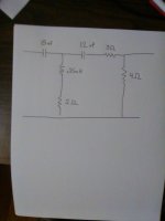
So, having got a sound I liked I then tried to replicate this with a passive crossover (using the -cap measurements and measured impedances)........and this is what I came up with.
 and with mid Inverted
This is basically a simple LR12 electrical topology which ends up being an acoustic LR24 on the woofer/mid crossover and LR12 on the Mid/Tweeter. There is a damping resistor on the mid with a shaping resistor in the low pass parallel leg. There is an L-pad on the tweeter. The resulting impedence curve looks manageable for most modern amps with a low of 3.2ohms at 110hz but is definitely a 4ohm design.
Now the bit where I would like a bit of critique of what I have done to tame the rising frequency response of the tweeter that is seen in many Morel units. I added a small inductor in series to tip over the curve at around 8Khz and then added a notch at around 10khz. This seems to flatten things off nicely but is having and inductor in series in a tweeter circuit a good idea and will it affect the sound negatively?
In general think the p[assive version matches the design aims and the active system fairly well.
Finally, before I splash some cash on crossover components to see if this scheme sounds as good as the active version (would be happy if it did), for the woofer inductor is it Ok to use a 1mm/18awg iron core coil or do I need to go 14awg Air coil and also for the 100uF capacitor is something like a Jantzen eLeCap 5% Electrolytic Bipolar Capacitor Ok to use or again do I need to go for a Jantzen CrossCap? Just trying to keep the cost sensible at the moment until I know it is Ok. The rest of the Caps are affordable using Jantzen Standard and the coils will be 18AWG Air Coils.
Anyway, congratulations for getting to the end, and thanks in advance for any comments left. Everyday is a school day for me!
Apologies this may be a long post.
Drivers - SB WO24P-4 woofer, Morel EM1308 Dome Mid, Morel ET448 Tweeter.
Box - Approx 40L sealed and medium stuffed with polyester toy stuffing. (re-purposed Akai SW125 box)
I finally got round to making a set of measurement the other day and have tweaked my active crossover to a point where I like the sound and theoretically it models well. The caveat here is that the room I have done the measurements in is not very large and has furniture in so quite a few reflections sothey are not perfect and have been smoothed. Measurement were taken at 1m at tweeter height and around 85dB loudness (roughly calibrated against mobile phone dB meter).
I took measurement from -90 to +90 degs for each of the drivers without moving the mic (note the Tweeter and Mid are both domes and so have protection capacitors, measurements taken with and with out these in place). I took nearfield for the woofer 1cm from the centre dust cap (sealed enclosure) and then impedance of each of the drivers in the box (with and without protection caps just for interest).
The results for the woofer seemed to suggest I am on the right track. The nearfield looks to be close to a Max Flat alignment which is what I was after. The 1m measurement aligns Ok with the manufacturer data and shows the baffle step below around 350hz (360mm wide baffle). Also the Impedance curve matches the Winisd output almost identically (peak : 32ohms at 47hz). So the box look pretty good for the WO24P-4 woofer.
I have been running a Minidsp Nanodigi crossover for a while and have had great fun playing with different slope filters and arrangements and also comparing it to crossover designs in VituixCad that seem to align quite well.
A quick check on the step/impulse response delays between the tweeter and the mid./woofer seem plausible at approx 5mm for tweeter to mid and 75mm for tweeter to woofer. So reference feedback seems to be working and has now embedded the acoustic offset into the phase measurements.
I then loaded up the +cap tweeter/mid and woofer measurements into VituixCad and played around with a few different designs with different slopes for an active crossover, these ranged from BW6 to LR24 in various combinations. The aim was to get a fairly flat on axis frequency response, align phase of each driver as close as I could (min 1 octave either side of the crossover point) and then have an in-room response that tried to follow a slope of 0.9dB/octave (or 6dB form 100hz to 10khz). Note, I did not merge the nearfield so it has room bass reflections under around 300hz.
Without documenting all of the various trials and errors, I settled on the following scheme that seems to meet most of the requirements quite well. To me this sounded the best subjectively, it has a fairly large soundstage with decent separation between the instruments and has a natural and lifelike presentation. I could stand the vocals being a little more forward but this is the only minor criticism. Bass is plentiful in my 10ft x 10ft x 8.5ft [ceiling] room with the speakers pushed a little into the corners.
So, having got a sound I liked I then tried to replicate this with a passive crossover (using the -cap measurements and measured impedances)........and this is what I came up with.
and with mid Inverted This is basically a simple LR12 electrical topology which ends up being an acoustic LR24 on the woofer/mid crossover and LR12 on the Mid/Tweeter. There is a damping resistor on the mid with a shaping resistor in the low pass parallel leg. There is an L-pad on the tweeter. The resulting impedence curve looks manageable for most modern amps with a low of 3.2ohms at 110hz but is definitely a 4ohm design.
Now the bit where I would like a bit of critique of what I have done to tame the rising frequency response of the tweeter that is seen in many Morel units. I added a small inductor in series to tip over the curve at around 8Khz and then added a notch at around 10khz. This seems to flatten things off nicely but is having and inductor in series in a tweeter circuit a good idea and will it affect the sound negatively?
In general think the p[assive version matches the design aims and the active system fairly well.
Finally, before I splash some cash on crossover components to see if this scheme sounds as good as the active version (would be happy if it did), for the woofer inductor is it Ok to use a 1mm/18awg iron core coil or do I need to go 14awg Air coil and also for the 100uF capacitor is something like a Jantzen eLeCap 5% Electrolytic Bipolar Capacitor Ok to use or again do I need to go for a Jantzen CrossCap? Just trying to keep the cost sensible at the moment until I know it is Ok. The rest of the Caps are affordable using Jantzen Standard and the coils will be 18AWG Air Coils.
Anyway, congratulations for getting to the end, and thanks in advance for any comments left. Everyday is a school day for me!

The passive Xover response looks more than promising, maybe slightly better than the DSP response to my eyes.
I cannot see an issue with the inductor feed to the tweeter. The impedance at 20KHz is maybe just turning upwards and definitely not going down, so fairly resistive which is kind to amplifiers.
As to the bass leg inductor I think it would need careful scrutiny and some calculations to decide if it were man enough for the job.
A chunky air core could be a safer bet without calculations . You are using a nice woofer up to 500Hz or thereabouts, consequently if the iron core saturated on bass peaks you should here it.
As to caps personally I would go with any of the well known makers of Bipolar cap, I am sure Jantzen make some nice ones, and the Mundorf that I have used have been good, but I haven't used a value as high as 100uF. Check manufacturers data for lowest ESR probably a plain foil type.
If you post an frd, and zma for the tweeter, I think I can make a simpler filter that will tame the top end.
I would avoid the Standard Zcaps unless you want an upper emphasis in the treble. Suffice to say they can make drivers sound shrill, or like stringed instruments are getting plucked or hammered HARD. They have been okay in some designs I've finished, but not all have sounded good using them.
CrossCaps are okay, as are Audyn Q4. Solen FC I find are better across woofers than the CrossCaps though. I would not place Solens in series with mids or tweeters though.
CrossCaps are okay, as are Audyn Q4. Solen FC I find are better across woofers than the CrossCaps though. I would not place Solens in series with mids or tweeters though.
Hello!for the woofer inductor is it Ok to use a 1mm/18awg iron core coil
Yes, for a 2.7mH iron core, 18AWG will give you low enough resistance.
You just need to pay attention on how much relative permeability you plan to use and the maximum magnetic flux density (B in Tesla) that will be present in the iron core.
Relative Permeability: The lower the better for linearity. In my experience, up to 10 or 15 gives you good linearity.
The relative permeability will be like a "gain" relative to the air core. If your air coil gives you 270uH, using a iron core with a relative permeability of 10, your final inductance, with the iron core, will be 10*270uH = 2.7mH. You adjust the relative permeability with an air gap or using an open magnetic circuit core such as a simple laminated iron rod, which will always have low relative permeability since magnetic lines close through the air, so with a lot of air gap.
Maximum B: for laminated iron core, the maximum is 1.5T where it starts to saturate. I design below 1T just to be safe.
Calculating B as function of L (inductance), I (current), N (turns) and A (area)
B=(L*I)/(N*A)
Example:
L=0.003mH
I=10A (this is the peak current through the inductor - not RMS, the real sine wave peak in time domain)
N=89 turns
A=0.02*0.02=0.0004m2 (this is the core section area)
B=(0.003*10)/(89*0.0004)
B=0.84T (below 1T, so it's ok!)
Toy stuffing does little to nothing unless it's wool or cotton. Try fiberglass, wool or cotton for damping, it will smooth out the midrange. Some purpose made fibers are OK but they have silica added to the fibers to help and are nowhere near as effective as wool.
@Arthur Jackson thanks for the comment but not sure how the stuffing will affect the midrange as the EM1308 is a sealed dome mid like a big tweeter and the WO24P-4 is rolled off at around 600Hz.
Many thanks for the comments, much appreciated and will do a bit more digging on the Iron Core inductors, the Jantzen ones are rated to 400W and I will be using these speakers no where near that.
@temp25 will post the tweeter FRD/ZMA later, thanks for the offer.
Many thanks for the comments, much appreciated and will do a bit more digging on the Iron Core inductors, the Jantzen ones are rated to 400W and I will be using these speakers no where near that.
@temp25 will post the tweeter FRD/ZMA later, thanks for the offer.
@temp25 Tweeter FRD/ZMA attached below (taken without protection capacitor). These were taken at 1m from the baffle at the centre line and tweeter height. This is for on-axis (0degs) and impedance taken in box (not that that makes much difference for a tweeter). No gating but psychoacoustic smoothing applied in REW.
I have also added pictures of the tweeter FRD and ZMA in REW plus at 0,30 and 60 degs off axis (note - tweeter is not central to the baffle therefore + and - provided) and also a blown up version of the crossover response for reference.


I have also added pictures of the tweeter FRD and ZMA in REW plus at 0,30 and 60 degs off axis (note - tweeter is not central to the baffle therefore + and - provided) and also a blown up version of the crossover response for reference.
Attachments
I couldn't get the files to work, but what I did was look at the filter transfer functions. I think I see what you want, but I'm not sure. Anyway, this filter topology might get close with some adjustments. The big thing is the padding is near the tweeter. This makes the crossover see a flat impedance.
Attachments
Thee Morel data shows a nice flat top end.
Everybody does things differently. Can I talk you into using gated measurements?
Everybody does things differently. Can I talk you into using gated measurements?
If needed, you could post files from REW. I have pretty good luck using them.
Do you ever use overlays for a response target?
Do you ever use overlays for a response target?
@temp25 Thanks for the pointer. I plugged in your tweeter scheme and it was pretty close.

I then tweaked a bit to get the in in-room closer to the target and also to align the phase a little, looks much simpler. The tweeter impedance dips down to 3.0ohms but that should be manageable with a good class D amp. Thanks.

In terms of gating I did look at applying this in REW post measurement and it does to seem to make a huge difference. Below is the impluse without and with gate at 4ms (1st big reflection) and then a comparison of ungated 1/12 smoothing, ungated psychoacoustic smoothing (one I am using) and gated 4ms 1/12 smoothing.


I have also added the tweeter and mid (no protection cap), woofer, nearfield and impedance REW MDAT files. I have had to cut the included measurements down to 0, /-30, +/-60 due to file sizes.
If you spot anything in them that is not correct please do let me know.
Thanks again for the help, much appreciated.
I then tweaked a bit to get the in in-room closer to the target and also to align the phase a little, looks much simpler. The tweeter impedance dips down to 3.0ohms but that should be manageable with a good class D amp. Thanks.
In terms of gating I did look at applying this in REW post measurement and it does to seem to make a huge difference. Below is the impluse without and with gate at 4ms (1st big reflection) and then a comparison of ungated 1/12 smoothing, ungated psychoacoustic smoothing (one I am using) and gated 4ms 1/12 smoothing.
I have also added the tweeter and mid (no protection cap), woofer, nearfield and impedance REW MDAT files. I have had to cut the included measurements down to 0, /-30, +/-60 due to file sizes.
If you spot anything in them that is not correct please do let me know.
Thanks again for the help, much appreciated.
Attachments
Try this. Instead of 4 ohms, and 3 ohms, try 8 ohms, and 3 ohms. Replace the 4 ohm with an 8 ohm. Then add a 2 ohm in front of the x-over. As long as there's some resistor across the tweeter, it will make the filter easier. (sometimes).
The 2 ohm I showed can be adjusted to change the shape of the roll-off, as can the cap values.
The 2 ohm I showed can be adjusted to change the shape of the roll-off, as can the cap values.
I tried adding the resistor before the xover and upping the parallel resistor but this introduced a bit of a dip around 6khz for some reason.
A little more tweaking with the values in the mid crossover to add a little to the tweeter impedance (now at 3.1ohms with woofer at 3.2ohm minimum).

A little more tweaking with the values in the mid crossover to add a little to the tweeter impedance (now at 3.1ohms with woofer at 3.2ohm minimum).
Just a quick sanity check, rough and ready measurements in my study (10x10ft 8.5ft ceiling, quite cluttered, not ideal.
Comparison of left and right drivers, confirms nothing is funky about the tweeter and it does indeed rise above about 8khz (as opposed to the Morel graphs).

Also played around with the active crossover and this looks reasonable.

So plugged this into the minidsp and ran a sweep on axis at 1m plus a sweep with the mid inverted and added a 4ms gate. I saved the frequency traces and imported them into VituixCad as overlays. Bass null look pretty much spot on, mid null look a little out but still pretty deep. I'll have a listen to this over the next week or so along with some others and see what my brain likes.


Comparison of left and right drivers, confirms nothing is funky about the tweeter and it does indeed rise above about 8khz (as opposed to the Morel graphs).
Also played around with the active crossover and this looks reasonable.
So plugged this into the minidsp and ran a sweep on axis at 1m plus a sweep with the mid inverted and added a 4ms gate. I saved the frequency traces and imported them into VituixCad as overlays. Bass null look pretty much spot on, mid null look a little out but still pretty deep. I'll have a listen to this over the next week or so along with some others and see what my brain likes.
If you want me to continue, post a zma for each driver. I can't get the REW exports to work for the impedance. I'm probably doing something wrong. I did get the sweeps turned into frd files. I made a x-over sim, but used incorrect impedance files.
Did you want the top end so bright?
To me, more forward is more SPL at around 1k.
Did you want the top end so bright?
To me, more forward is more SPL at around 1k.
Last edited:
@temp25 I really appreciate your help and the time you are spending on this, many thanks.
I have added the separate zma's (.txt files so may need renaming), otherwise I have used the " File > Export > Export Measurement as text " function which seems to give a frequency/impedance/phase zma output.
In terms of brightness, I don't find it too bright in my room which seems to be born out by the "in room" simulation (orange curve, middle left pane) but the on axis looks like it has quite a bit above 8khz but this is tamed in-room. Agreed, adding a bit around the 1khz will bring out the vocals.
I probably ought to have said that I mainly listen to prog metal, prog rock and some other forms of metal (Ambient, Doom, Metalcore, Djent, Thall etc. and post rock/metal). So, some of these recordings are pretty dense but some are very well recorded contrary to popular belief (The Steven Wilson engineered Opeth albums are excellent, try Damnation). But in general these tend to need fast/dynamic bass for the kick drums but also a bit of a boost up top to bring out the cymbals, vocals are often back a bit in the mix as well as they are more seen as another instrument in metal rather than the star of the show (e.g. Tool). Anyway, this may help understand why I like the sounds I do.
I have a three of four crossovers with different attributes that i will be listening to over the next couple of days (active models) to see if I can pinpoint where I need to add/remove.
Thanks again.
Attachments
Last edited:
If I get chance tomorrow evening I will dig out my old version of PCD and see if I can load them in, they go into VituixCad fine. One last try I would be to open up the pictures in Vituix and re-trace them in and output the zma fro there. Will send those through to see if that works.
Your model looks good on axis, nice an flat, I see you added notches in the bass and mid and then brought down the last octave. What slopes are you using for the low/high pass. You also settled on similar crossover points as I did, around 800hz and 3.5khz. Based on the distortion plats the mid should not be used below about 700hz and the tweeter below about 2khz and conversely the woofer is Ok up to about 1khz which is about an octave below where it starts to beam badly and two octaves below the start of the break up at around 4-5khz. So there are fairly obvious crossover points for these drivers.
Thanks again.
edit - traced XMA added, see how that goes.
Attachments
Last edited:
- Home
- Loudspeakers
- Multi-Way
- Crossover Comments Please