I posted this last week in the power supply forum but did not get any input. It seems most of the post there relating to the solid power supply. Perhaps I have posted in the wrong forum!
I got this power supply advertised as power up condition only and currently tried to restore it. Replaced some components, weak tubes and checked most of them too. In general most of the components are still within the tolerance. Some exceeded slightly but I don't think it will cause much of the problem and did not replace them. Did not replace any Bumblebee caps since they're still within the tolerance (using LCR meter).
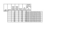
Attached is the output data after power it up. The main issue is it did not reach the max voltage except as noted in my file. Checked all resistors in the sampling network. They are fine. Negative 250V Bias is fine. I also checked out all parameters per Figure 4-2- Tube Voltage Chart on page 4-3 of the Maintenance section. The voltages are not really matched what specified there and don't know and not sure if they are really related to the issue that I have. One thing that's quite different from what specified in the chart is the pin 9 of V14 (6AU8). The chart said -61V on pin 9. It's measured about -61 voltage when Output Switch Position (0-500V) is in the "0" position only and I don't believe it's correct in other positions. My measurement on pin 9 started to turn to positive voltage when Output Switch Position (0-500V) dialed to position 100 to 500. On "500" position it measured about positive 289V. May be it's a typo perhaps.
One thing I noted is that on the cold day the output voltage increases from 15 to 30 voltages on "300-500" position scale. Thermal run away in some components??
I plan to take the Amplifier board out and replace all the components there. But before I do that I want to run through this forum for idea and input.
Appreciated with the help. Thank you.
I got this power supply advertised as power up condition only and currently tried to restore it. Replaced some components, weak tubes and checked most of them too. In general most of the components are still within the tolerance. Some exceeded slightly but I don't think it will cause much of the problem and did not replace them. Did not replace any Bumblebee caps since they're still within the tolerance (using LCR meter).
Attached is the output data after power it up. The main issue is it did not reach the max voltage except as noted in my file. Checked all resistors in the sampling network. They are fine. Negative 250V Bias is fine. I also checked out all parameters per Figure 4-2- Tube Voltage Chart on page 4-3 of the Maintenance section. The voltages are not really matched what specified there and don't know and not sure if they are really related to the issue that I have. One thing that's quite different from what specified in the chart is the pin 9 of V14 (6AU8). The chart said -61V on pin 9. It's measured about -61 voltage when Output Switch Position (0-500V) is in the "0" position only and I don't believe it's correct in other positions. My measurement on pin 9 started to turn to positive voltage when Output Switch Position (0-500V) dialed to position 100 to 500. On "500" position it measured about positive 289V. May be it's a typo perhaps.
One thing I noted is that on the cold day the output voltage increases from 15 to 30 voltages on "300-500" position scale. Thermal run away in some components??
I plan to take the Amplifier board out and replace all the components there. But before I do that I want to run through this forum for idea and input.
Appreciated with the help. Thank you.
Attachments
I have a Fluke 407D and use it often. It was working when I got it 10 years ago and still works today. It did die abruptly one day a few years ago. The power supply was sold as "untested" on Ebay for $25. It cost $45 to get it here from California. The meter switch had a broken wafer which I fixed with some JB Weld. It still has all of the original tubes in it, and judging from the undisturbed dirt inside, I believe that it had never been serviced. As many people here know, I tend to disrespect specs and limits, and I often ran the poor Fluke with the current meter needle pegged and it never wavered.
It died one day when it started outputting TOO MUCH voltage with a good deal of ripple. I spent too much time reading the manual and comparing voltages to the chart, before I resorted to my usual method of troubleshooting 50+ year old electronics stuff, bridge each electrolytic with something similar in capacitance and equal or higher in voltage rating. The old electrolytics dry out and lose value or just go open. It turned out that one of the can caps mounted to the chassis was open. I simply soldered my test cap in place, put the cover back on and it still works good today.
Those old "bumble bee" black caps with colored stripes also have a reputation for becoming leaky (electrically) or developing a crack in the case which usually results in loss of capacitance, or a dead short. I changed plenty of those in TV's, radios, and amplifiers in the 60's and later, but my 407D still has all of the original parts, it just has one extra cap.
First make sure that the negative voltage supply is operational and delivers about 250 volts when turned up all the way. Make sure that the 5651 tube is glowing. Both of these need to work in order for the positive voltages to be right.
Simple Dumm Blonde troubleshooting method for old electronics equipment. Bridge each electrolytic with a new cap and test for functionality. In things like this power supply with lethal voltage levels, use clip leads to connect the test cap across the suspect cap. Make sure the polarity is correct. If than fails, take voltage measurements. I clip lead the negative meter lead on ground, and probe parts with the positive lead. This does take more effort than poking around with both probes, but requires only one hand in the equipment. Do not touch the unit with the other hand. Any capacitor with the same voltage on either end should be suspect unless the schematic or other evidence shows this to be normal.
George,
Yes, both negative 250 voltage and the 5651 tubes are working. 86V is measured across the 5651 tube (right on within the spec of the tube).
Yes, both negative 250 voltage and the 5651 tubes are working. 86V is measured across the 5651 tube (right on within the spec of the tube).
I had one, measured several percent error from set voltage, more at the low end. Replaced three bumblebee capacitors and it was within 0.5% at every setting.
Tom,
I have a question. Can you verify that the neon lights V4, V5 and V11 are light up during normal operation while V6 and V7 Off? I noted that V6 & V7 are momentary light up when power supply just started to turn on and off during normal operation. I just want to make sure this is how it works. Thanks.
Today I just took the amplifier board out and tried to replace all the components on this board. All bumblebee caps are actually within the tolerance as I have mentioned early. Only one is slight off. However, I will replace them all any way. Hopefully it works this time.
Was years ago - I don't recall if I ever had it open while powered up. I have a scan of the manual, but not on my laptop. The bumblebees had DC leakage, like every other one I have measured.
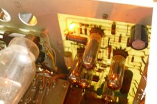
Picture from the top, operational, but unloaded. Board with fat power transistor and no tubes has 4 neon bulbs. Top two are always lit. The bottom two are not lit except for a flash at power up, and flashes when clicking the voltage range switch downward or if the output is shorted. No flash when range switch is clicked upward.
Single bulb near the 6AQ5 tube is always lit.
Want any more pictures while I have it halfway out of its case. This thing was dropped, sat, stepped on, or all three somewhere in its life before I got it. Getting it in and out of the case is not easy.
My memory is a bit foggy. This unit does not have Bumble Bee caps. It does have black Spragues that may be of similar construction. The Bumble Bees might have been in my Knight Kit power supply which I did totally recap 10 years ago, or a Paco which I gave away because it was too wimpy.
Attachments

Do you have one or two modern cheap hand-held battery powered digital meters that you can clip across points in the schematic before powering up, and then much more confidently (and safely) measure important operating levels - compared to probing in a live situation and adding or subtracting individual measurements to derive an important operating level?
For example, knowing that the regulating 807's had balanced cathode currents (ie. voltage across R8, R9, R10) and that screen voltage to cathode was as expected, would be a good start.
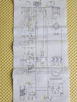
All your measured output terminal voltages don't reach their max range specs, that would imply there may be a common output voltage level feedback alignment error, which may mean focussing on the circuitry around the 0V adjust. Can you set the 0V level for all ranges? Did you swap 12AX7 V13 and get the same situation (ie. leakage or balance issues from the 12AX7 triodes)? Did you disconnect or swap C31 (ie. leakage through C31) ? Same with C32. Did you swap V14?
For example, knowing that the regulating 807's had balanced cathode currents (ie. voltage across R8, R9, R10) and that screen voltage to cathode was as expected, would be a good start.
All your measured output terminal voltages don't reach their max range specs, that would imply there may be a common output voltage level feedback alignment error, which may mean focussing on the circuitry around the 0V adjust. Can you set the 0V level for all ranges? Did you swap 12AX7 V13 and get the same situation (ie. leakage or balance issues from the 12AX7 triodes)? Did you disconnect or swap C31 (ie. leakage through C31) ? Same with C32. Did you swap V14?
George and Tom,
Thanks all for the info and inputs. My power supply was probably older unit since it does not have Silkscreen on a PCB at all compared to other units that I have seen across the web. I finally tear down the amplifier board and replaced all carbon resistors with 1% film resistors (that's what I have in stock) except for some precision resistors there. All bumblebees capacitors are also replaced with film caps even thought most of the resistors and capacitors are still within the tolerance.
Cross my figures and Fired up again. This overhaul finally paid off. Now it works as it should. All ranges are very accurate. Don't really know which components contributed to the problem. May be carbon resistors are drifting due to thermal and capacitors are leaking during operation but not shown up out of circuit measurement.
Imho, still worthwhile doing periodic checking that the three 807's are contributing somewhat balanced current levels - especially towards the 300mA maximum output capability of the supply.
Also note that the screen supply has no dedicated bleed resistor - which could be a hazard unless you add one.
Also note that the screen supply has no dedicated bleed resistor - which could be a hazard unless you add one.
Trobbins,
Thanks for the inputs. Yes it's good idea to add the bleeding resistor there. I took the measurement on all pins while working on this yesterday
One thing that's still puzzled me is that the plate voltage of V14 (6AU8) exceeded far beyond the specification after I took the measurement per page 4-3 of the manual. I am very sure the negative -61 volts there is a typo and it's only applied when Output Switch Position (0-500V) is in the "0" position only.
Pin 9 plate of V14 measured about positive +444 Volt when it's in "500" position and it should be since it's driving the grid of 807 tube. Pin 6 cathode pin of V14 measured about negative -101.4 volt. It meant its potential between plate to cathode is about 545 volt. This really exceeded the spec of 6AU8 which specified of 300V.
Can someone explain? And did I overlook something? Thanks
V14/9 is effectively the voltage of 807 grid, which is identified as 443V, or about 61v below 500V nominal output for that table. So yes the table has a glitch.
The operating Vak seems to be a max of 443+96. Note that the 6au8 data sheet plate curves extend well above 300V, so Fluke likely confirmed reliable idle operation out to that level.
The operating Vak seems to be a max of 443+96. Note that the 6au8 data sheet plate curves extend well above 300V, so Fluke likely confirmed reliable idle operation out to that level.
No I have not tube roll V14 and I have only tested it at 117VAC line voltage using Variac. My area line voltage is typically 120-121VAC. I might try to reduce it to 115VAC to match with input specification and again at 121VAC to see if there's a major in spread of measurement.
- Home
- Amplifiers
- Tubes / Valves
- Need Help in troubleshooting Fluke 407D Tube power supply