Hi,
Have this amp for a repair. No class D switching, nothing in short.
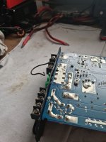
Was mounted freely in a trunk, an object hit it really hard looking at the deformed metal heatsink.
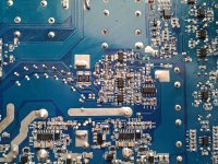
SMD caps C117, C141, C102 were cracked/split in half, maybe I will find more like those while poking around. Does anybody has schematics around the PWM / flip flop ic section or can tell me what are the values for those smd caps in the attached picture ?
Have this amp for a repair. No class D switching, nothing in short.
Was mounted freely in a trunk, an object hit it really hard looking at the deformed metal heatsink.
SMD caps C117, C141, C102 were cracked/split in half, maybe I will find more like those while poking around. Does anybody has schematics around the PWM / flip flop ic section or can tell me what are the values for those smd caps in the attached picture ?
Attachments

The information I have doesn't have C114 or C141 so it's not likely the same as your amp.
The amp has 2 circuits for the output. Dod the corresponding caps for the other circuit survive so you could measure those to find their values?
Contact Rockford to see if they can help.
The amp has 2 circuits for the output. Dod the corresponding caps for the other circuit survive so you could measure those to find their values?
Contact Rockford to see if they can help.
They have few different revision and there are differences. That's why i've posted the revision in the picture attached.
Not sure what survived and what not...Can confirm the PS section works now, but there is nothing at the irs20957s input pin 3. No PWM.
R140 + R139 + R138 are 2512 resistors 16 and 27 ohms, also cracked, there are signs of burning around those pads too.
I've already did some work in the PS section thanks to the attached schematics found in the forum here. But found only the PS section.
Attachments
Last edited:
Do you have a 1000pf capacitor?
If so, try it in the C114 location. Does that get you the square wave output?
If so, try it in the C114 location. Does that get you the square wave output?
I've replaced the caps with 1nf.
I do have switching now at one of the amplifier (it's a full bridge) the other one has 10v of DC at the input, pin 3.
While amps starts R140 + R139 + R138 are getting extremely hot and burns, I'm using now thru hole higher wattage resistor not the smd ones, as they don't survive the initial start up procedure. I suppose this happens due to the imbalance of the both amps being in a full bridge configuration and one of them working as it should but other one not.
It gets it from U101 which is LM393 pin 1 = 180khz square wave. It's tied thru some diode/zener and 100ohm resistor to pin 3 of the irs20957s
The 393 gets it from the 4013, doesn't it? One of the Q or not Q terminals?
180k is probably too high. On notes from a JX500, the oscillation for the outputs is 83k. This could be part of the problem with failing parts, although I don't know what R140 + R139 + R138 are in your amp.
180k is probably too high. On notes from a JX500, the oscillation for the outputs is 83k. This could be part of the problem with failing parts, although I don't know what R140 + R139 + R138 are in your amp.
Okay, i've had some progress, following the traces and drawing some schematics thru trial and error I could figure out some of the smd capacitors capacitance.
Now I do have all of the CD4013BM waves, just not sure if they are correct, nevertheless...i still don't have any switching at the second amplifier section.
I've traced as much as I could, swapped NE5532 + LM393 with new ones but no change. All of the resistors are in tolerance.
With no RCA signal coming in and using main GND as a referance
NE5532:
1 = 30v DC
2 = 35v DC
3 = 35v DC
4 = 12.7v DC
5 = 33.6v DC
6 = 34.2v DC
7 = 14v DC
8 = 48v DC
LM 393 (Pin 3 and 5 are tied together) :
1 = 7v square wave (95kHz) pin 3 of the irs20957s IC1
2 = 31v DC - tied thru 8,2kOhm to the output inductor for IC1 (i suppose it's the feedback circuit) + it get's the input from the pre amp from NE5532
3 = 31v Triangle (95Khz) thru some caps and resistors to CD4013BM
4 = 0v (GND)
5 = 31v Triangle (95Khz) CD4013BM
6 = 16v DC - tied thru 8,2kOhm to the output inductor for IC2 (i suppose it's the feedback circuit) + it get's the input from the pre amp from NE5532
7 = 9.6v DC - tied directly to pin 3 of the irs20957s IC2
8 = 36v DC
There are also a lot of zeners in the region, they are not shorted, but how I know if the regulate properly ?
DCV from pin 4 (black) to pin 2 for both 20957 ICs? - both 10v
Are the output FETs in the amp? = yes
Are the output FETs in the amp? = yes
No output drive from IC1?
Check high and low output.
Do you have supply voltage on pin 11, black on pin 9 for IC1? Check both ICs.
Check high and low output.
Do you have supply voltage on pin 11, black on pin 9 for IC1? Check both ICs.
IC1 works fine.
IC2 - no output, neither LO or HO .
Both IC have exactly 12.5v as a supply voltage.
I don't think IC2 will produce anything if pin 3 IN is just DC.
I've even removed the IC2 and checked again the pad for pin 3 - still 9.6v DC present.
IC2 - no output, neither LO or HO .
Both IC have exactly 12.5v as a supply voltage.
I don't think IC2 will produce anything if pin 3 IN is just DC.
I've even removed the IC2 and checked again the pad for pin 3 - still 9.6v DC present.
You're right about the DC drive for the 20957.
For the op-amp driving the 393, follow pin 5's circuit back. Do you see a 4.7k resistor and a 10uf capacitor and then another op-amp output?
For the op-amp driving the 393, follow pin 5's circuit back. Do you see a 4.7k resistor and a 10uf capacitor and then another op-amp output?
NE5532 Pin 3 and 5 are tied, separately, thru a 4.2k resistor and 10uf electrolytic cap to the output of the entire pre amp section. The preamp section is producing clear sinewave if I feed the RCA.For the op-amp driving the 393, follow pin 5's circuit back. Do you see a 4.7k resistor and a 10uf capacitor and then another op-amp output?
What happens if you play a tone 40hz thru the RCA at the NE5532 near the LM393 (NE feeds the LM at least to my tracing and understanding):
1 = 30v DC - sinewave present (rides on the top of the 30v)
2 = 35v DC - no sinewave
3 = 35v DC - no sinewave
4 = 12.7v DC
5 = 33.6v DC - (rides on the top of the 33v)
6 = 34.2v DC - (rides on the top of the 34v)
7 = 14v DC - no sinewave
8 = 48v DC
So why there would be no output from pin 7 ? Should be voltage driven, not current, correct ? Maybe pin 5 and 6 are out of phase and they cancel each out ?
- Home
- General Interest
- Car Audio
- Rockford Prime 1000.1D - identifying smd caps