When the line is long.
This could just go on for a while. https://www.diyaudio.com/community/threads/questions-about-transmission-line-speakers.326546/
This could just go on for a while. https://www.diyaudio.com/community/threads/questions-about-transmission-line-speakers.326546/
Last edited:
I guess it doesn't matter.Is it correct?
That's what I tried to point out in my post #882.
A resonator doesn't care whether you call it transmission line or bass reflex or mass loaded quarter wave resonator or whatever.
That's the beauty of being able to simulate and get identical results with different (but converging) setups.
(Just try to ask a tapped horn whether it likes to be called a serial 6th order bandpass 😊)
Last edited:
Is it correct?
Something has to physically distinguish a BR from a TL.
Options are:
Port volume in relation to enclosure volume,
Port length,
Since ports are used to enhance bass and the lowest note on a 4 string bass is 41hz, then the 6 foot (72 inch) length has a strong argument.
So when does a BR turn into TL?
It's a bit like asking: "How long is a piece of string?" 🙂
As far as the physics is concerned it would be fair to say that it is when the dimensions of the port tube become such that the air contained in the duct no longer acts primarily as an acoustic mass, that is, it becomes compressible.
For a bass reflex system:
Helmholtz resonance frequency = 1 / (2 * Pi * (Ma * Ca) ^ 0.5)
Where:
Ma = Port tube acoustic mass (including end corrections) in kg / m ^ 4
Ca = Enclosure acoustic compliance in m ^ 5 / newton
Numerical example:
Ma = 100 kg / m ^ 4
Ca = 10 ^ -7 m ^ 5 / newton
f = 1 / (2 * Pi * (100 * 10 ^ -7) ^ 0.5)
f = 50 Hz
😊spreadsheet for best port placement!
I will post some measurements and hornresp simulations of the subwoofer in the image above!
The offset port transmission line model in hornresp is a great tool for finding the best port and driver positioning (and filling!) for bass reflex enclosures.
You proved by simulation what I learned from trial and error. Pick a woofer where the largish box can be tuned below 30hz and build a 3 way where the woofer is crossed below 300hz. However, it is cool to take a 12" prosound woofer tuned to 50hz run some bass heavy music at higher spl and feel the port air movement. Remember the old parlor trick of blowing out a candle with the bass port? LOL fun with distortion. Try that with a 30hz tunning, you'll be running for cover.A link regarding (industrial) resonance absorbers, as proposed at the beginning of this thread - helmholtz and quarter wave variants:
https://deicon.com/solutions/vibration-isolation/tuned-acoustic-absorbers/
I am currently "procrastinating" and doing a small research to underestand the transition from a helmholtz resonator to a quarter wave resonator.
I already had this in mind for some time and was reminded because of the apparent limits of bass reflex enclosures in case of big volumes and high outputs (see @tmuikku's subwoofer project). such speakers require very big ports for correct tuning and sensible compression/chuffing behaviour. The ports are huge, also related to the enclosure dimensions and clear distinction between "enclosure" and "port" is getting questionable.
1) hornresp simulation of different helmholtz resonators (bass reflex enclosures) tuned to 30 Hz
the variants have very different enclosure volumes and correspondingly different port lenghts.
I deliberately chose a small 4" driver to make the helmholtz resonance as independent from the driver as possible. at least in my understanding ...
View attachment 1441910
some observations:
- despite the same tuning frequency (according to hornresp loudspeaker wizard) the resonance peak frequency differs slightly.
- big enclosures with small ports have a more pronounced resonance peak
- the small enclosure big port variants have very strong and (obviously) lower frequency port resonance peaks.
2) small and big enclosure with similar peak frequency
to compare the small and big enclosure with similar peak frequency I adjusted the big enclosure tuning:
View attachment 1441919
the big enclosure resonance peak is still more peaky.
2) increasing the port size for a fixed enclosure and tuning
these are simulations of a PA woofer bass reflex enclosure (and one TL, for comparison).
the net enclosure is the same for all variants.
the port cross section surface and port lenght increase with every step, keeping the tuning the same.
use the arrow buttons to scroll through the variants (or swipe on the phone).
View attachment 1441922
View attachment 1441923
View attachment 1441924
View attachment 1441925
View attachment 1441926
View attachment 1441927
View attachment 1441928
same simulation, but lossless, for caomparison to TL:
View attachment 1441929
simulation of a simple transmission line with similar (same) dimensions.
the second transmission line section is slightly longer than the port to compensate for end correction of bass reflex port.
View attachment 1441930
observations:
- hornresp apparently does not allow making the bass reflex enclosure a "virtual transmission line" (it states the port is "too big"). thus the BR port and second TL section surface is "only" 1600 cm2.
- there seems to be a smooth transition between bass reflex enclosure (helmholtz resonator) and transmission line (quarter wave resonator). It seems impossible to draw an exact line where a bass reflex enclosure turns into a quarter wave resonator and vice versa. In other words it's a semantic rather than technical distinction.
- contrary to the simulation above the long port results in a more pronounced peak.
- obviously the big port or TL lead to strong resonances: first (desired) resonance at 1/4 wavelength and the second (unwanted) resonance at 3/4 WL.
Well, it's all just about definition I suppose 😀A link regarding (industrial) resonance absorbers, as proposed at the beginning of this thread - helmholtz and quarter wave variants:
https://deicon.com/solutions/vibration-isolation/tuned-acoustic-absorbers/
I am currently "procrastinating" and doing a small research to underestand the transition from a helmholtz resonator to a quarter wave resonator.
I already had this in mind for some time and was reminded because of the apparent limits of bass reflex enclosures in case of big volumes and high outputs (see @tmuikku's subwoofer project). such speakers require very big ports for correct tuning and sensible compression/chuffing behaviour. The ports are huge, also related to the enclosure dimensions and clear distinction between "enclosure" and "port" is getting questionable.
1) hornresp simulation of different helmholtz resonators (bass reflex enclosures) tuned to 30 Hz
the variants have very different enclosure volumes and correspondingly different port lenghts.
I deliberately chose a small 4" driver to make the helmholtz resonance as independent from the driver as possible. at least in my understanding ...
View attachment 1441910
some observations:
- despite the same tuning frequency (according to hornresp loudspeaker wizard) the resonance peak frequency differs slightly.
- big enclosures with small ports have a more pronounced resonance peak
- the small enclosure big port variants have very strong and (obviously) lower frequency port resonance peaks.
2) small and big enclosure with similar peak frequency
to compare the small and big enclosure with similar peak frequency I adjusted the big enclosure tuning:
View attachment 1441919
the big enclosure resonance peak is still more peaky.
2) increasing the port size for a fixed enclosure and tuning
these are simulations of a PA woofer bass reflex enclosure (and one TL, for comparison).
the net enclosure is the same for all variants.
the port cross section surface and port lenght increase with every step, keeping the tuning the same.
use the arrow buttons to scroll through the variants (or swipe on the phone).
View attachment 1441922
View attachment 1441923
View attachment 1441924
View attachment 1441925
View attachment 1441926
View attachment 1441927
View attachment 1441928
same simulation, but lossless, for caomparison to TL:
View attachment 1441929
simulation of a simple transmission line with similar (same) dimensions.
the second transmission line section is slightly longer than the port to compensate for end correction of bass reflex port.
View attachment 1441930
observations:
- hornresp apparently does not allow making the bass reflex enclosure a "virtual transmission line" (it states the port is "too big"). thus the BR port and second TL section surface is "only" 1600 cm2.
- there seems to be a smooth transition between bass reflex enclosure (helmholtz resonator) and transmission line (quarter wave resonator). It seems impossible to draw an exact line where a bass reflex enclosure turns into a quarter wave resonator and vice versa. In other words it's a semantic rather than technical distinction.
- contrary to the simulation above the long port results in a more pronounced peak.
- obviously the big port or TL lead to strong resonances: first (desired) resonance at 1/4 wavelength and the second (unwanted) resonance at 3/4 WL.
But yes, if we just look at everything from a piston perspective, from a pure practical view, a TL is nothing more than a BR with a volume shape that is less ideal in sense of total volume. (if that makes sense)
We're just going from a rectangular box to a more triangle shaped box.
Purely speaking, the comparison isn't quite fair.
BR simulations only look at just lumped-circuit piston behavior.
Resonances and other practical considerations are not part of that, since they belong in that "domain".
From there you gradually go into more acoustic behavior = TL.
In a sense everything is a transmission line.
Not just for acoustics, but this counts for many many other things as well.
(like mechanical behavior, electronics etc)
If I understand correctly hornresp is an exception here, because it includes port and main enclosure dimension resonances.BR simulations only look at just lumped-circuit piston behavior.
Last edited:
If I understand correctly hornresp is an exception here
You understand correctly 🙂. Hornresp calculates acoustic pressure, volume velocity and impedance values for bass reflex port tubes and transmission lines using the same model. It's just that the dimensions of a port tube are normally such that the air acts primarily as an acoustic mass, as demonstrated in Post #907.
I had some time to think and simulate and I guess there is not even the need for a spreadsheet! At least for the very fundamental rules.Now @stv has to make a spreadsheet for best port placement!
And I am sure I am not at all the first one to find this "solution".
General requirements:
- keep efficiency of the desired bass reflex resonator high (thus, as little stuffing material as possible)
- generate as few resonances as possible
- avoid resonances exiting through the port (and the driver, but the port usually better transmits resonances)
- try to move resonances up in frequency, where they are easier to dampen with (thinner) stuffing/lining material
1. avoid lowest resonance
the stronger and difficult to tame resonances are the low ones.so let's try to avoid the lowest resonance in a given enclosure.
lowest possible resonance is the first mode generated by a wave travelling back and forth along the longest box dimension (λ=2*L).
if we place the driver at the exact half length of the longest box dimension, the waves travelling in both directions will coincide and cancel out at the driver position.
we have "virtually" halved the longest box mode!
there is, of course, still a resonance with double that frequency (λ=1*L).
2. avoid the resonance exiting the port
the resonance mentioned above with λ=1*L is still strong (and it does indeed affect the driver, which hopefully will be able to handle it).how to avoid it exiting the port?
put the port in a position far from pressure peaks (enclosure walls and driver), that is: at a quarter of the enclosure length.
3. dampen the rest of the resonances with lining/stuffing
4. if you are not happy with the driver and port positions for aesthetic or practical reasons
use a tapered enclosure or divide it creating a taper. this allows to change the ideal driver/port positions (simulations will follow!).using the hornresp offset port transmission line model is great for simulating this!
alternatively: switch port and driver positions. this seems to be just very slightly worse.
5. it even seems possible to cancel out enclosure and port resonances in simulation
but I am not sure how well that translates to reality!Hornresp simulations
a) worst case: driver at one end of a long enclosure, port at the other end
with strong first longitudinal mode resonance at λ=2*L (~ 283 Hz):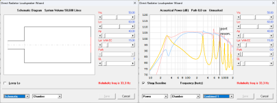
b) better variant with both port and driver at half enclosure length (front/back, for example):
first visible resonance one octave higher up at λ=1*L (~ 567 Hz).resonance peak can be lowered with filling, also lowering the bass reflex output (here about -2 dB):
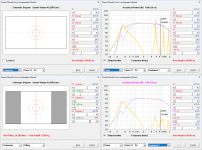
c) even better with driver at half and port at quarter length and vice versa:
very thin peaks, easily dampened with a bit of lining.bottom variant has a stronger resonance in the total output (red) at 283 Hz. that is because the longitudinal mode is excited by driver not mounted in the center and can excite first mode.
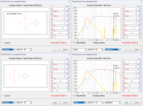
upper variant with filling:
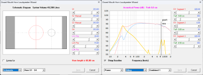
d) a quick attempt to cancel enclosure and port resonance:
but not sure if it's worth it - it definitely needs some more optimising work!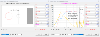
... and a measurement, just to confirm simulations
this was one of the first and bad versions of the enclosure shown in my last posts and should prove how good the simulations work for the main, lower resonance(s):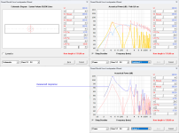
of course there are several more resonances created by other dimensions in a real enclosure, interfering and making simulation at higher frequencies less accurate.
I am happy about any hints or suggestions!
Last edited:
Don't use (read:think) the software to show "the exception". 🙂If I understand correctly hornresp is an exception here, because it includes port and main enclosure dimension resonances.
What's important is how it works under the hood.
Let me explain in a far more practical question.
If I know for sure that I am gonna crossover the driver far below the first mode of the cabinet (resonance issue, or whatever other problem)
Does it matter what kind of system it really is? (assuming all other variables are exactly the same).
Answer: no, because the behavior of the system has the same roll-off, slope and Q-factor, therefor (as a fact) it IS and must be the same system.
So yes, in a sense Hornresp is different in a way.
It's kinda in between a BEM/FEM analyses and just plain lumped-circuit. (if you wanna think about it that way)
What's important to understand is that neither of the two is better or wrong.
Because acoustic systems still work and act like (higher order) mass-damping-spring systems.
Just for (non-linear) acoustic problems that model is a bit limited, hence working with transmission-line mathematics is a bit more useful.
Or if you need to go even more fancy, go to BEM/FEM analysis (= brute force basically).
On the other hand, how far do you want to go with calculations?
Because there are always two options:
1 - mitigate and tackle the problem
2 - simply avoid the problem
In the context of loudspeakers and such resonance problems, that's mostly with only (small) 2-way or 2.5-way systems that need some kind of port/PR.
One of the reasons why a FAST system isn't such a crazy idea.
Because if we go for option 2, transmission-line mathematics aren't all that useful anymore since we are very far removed from those kind of issues anyway.
Therefore we can just simplify the problem.
In room-acoustics, we use the term Schroeder frequency.
Inside a cabinet (or any other mechanical problem or behavior) it's exactly the same thing.
Aka: the transition from where sound waves act similar like static air pressure to the zone where acoustic resonances dominate.
Last edited:
I don't know of another enclosure simulation program that is a user friendly that has this capability. And has the level of testing out in terms of simulation versus measurements. It's a very solid program once you get to understand how it works. Under help there is an input wizard. It's a fast way to get to where you want to go right off the beginning. There will be a simulation of the enclosure type that you want. But not your driver parameters which you will need to enter. The the vent dimensions and the port length.If I understand correctly hornresp is an exception here, because it includes port and main enclosure dimension resonances.
Question guys: Why not look at cabinet and port resonances with the planned low-pass filter in place?
Seems to me they'll only resonate if excited.
In Hornresp, once I add a low-pass to a sub with the filter wizard, resonances go bye-bye...looks like masked.
Masked look is for subs that are being used as subs, low-passed say no higher than 200Hz,
......not to a woofer trying to reach much further up (which I never fool with)
- Home
- Loudspeakers
- Multi-Way
- Investigating port resonance absorbers and port geometries