Has anybody built a set up for KT88/6550, 300B, or 845 who could share experiences and ideally, a BOM and what you did for supply voltages? I think there was talk of tailored BOMs, but it looks to me like the thread never got that far, even for the KT88/6550.
Paul
Paul
I have a pair of stuffed boards here and I would be keenly interested in seeing a KT88 version built and documented as well.
To my girlfriends annoyance the kitchen table is currently decorated with a mix of 6080's.......This was my kitchen table Friday...
I don't think I have ever had electronics stuff on the kitchen table, but maybe I did and don't remember......My best test of my wife's patience was building an automobile engine, and rebuilding the transaxle in the middle of the living room floor. This was a project that took about 3 weeks and we had a teenage daughter at the time. All of the parts were either new, or thoroughly cleaned so there was no serious mess, but the house was a serious obstacle...
There's some info here.
I know that it once existed as I made a video of it running. Now, if I could only find my notes. Video is here:I would be keenly interested in seeing a KT88 version built and documented as well.
I have been contemplating the construction of "The BIG one" for some time. If I can get all the other stuff off the bench, I'll try the UDB + UNSET Octal Output Board combination. Once that is stable and working, it's only a matter of adding more UNSET output boards and building a power supply capable of feeding a 1KW tube amp.
I have been enjoying the KT88 mono-blocks I built with using the UDB boards for several years now. They sound great. Attached is a version of the BOM, (I'm guessing it is the final one) along with a schematic that George drew of the power supply needed. I hope this is helpful. Enjoy
Attachments
The original Universal Driver Board has a long and winding story behind it with some long periods of time where it was ignored. I had created an amp called the 300Beast in about 2000 in which I simply cut and pasted some of the trendiest circuits found on the web together. Despite having far too much gain, it worked pretty good but fell into disuse and got stripped for parts a few years back. The first two stages were the starting point for a new P-P driver design.
The first iteration of the UDB was made on a turret board in 2007. I slapped it together so I could test some big sweep tubes in conventional G1 drive as well as screen (G2) drive applications where huge AC drive voltages are needed. Despite the obvious physical differences, both tubes were always 6SN7's. This thing went through several changes as the needs dictated and got used a lot. There was obviously at least one attempt at a PC board back in 2007 and KT88's were involved. 2007 and 2008 brought a lot of challenges with the death of my father and Sherri's stepfather, a bout with recurring aggressive skin cancer and a job change. The board sat on the bench unused a lot.
In 2008 I had begun to tinker with tubes again and a question was asked on diyAudio which got the board out of the box where unused boards go to be relieved of useful parts. That happened in post #94 in this thread which evolved into a Push Pull 6L6GC amp in Australia, and the UDB here over nearly 4 years.
By 2010 I could see that Motorola was on a long slow downsizing / offshoring of the plant where I worked, and tech in general was dying off in South Florida so plans were put in motion for my eventual retirement which did come far earlier than I expected. There were several road and air trips between South Florida and West Virginia with lots of down time due to health issues with relatives. I used that time to lay out PC boards on my laptop. I still have at least 20 completed or partially completed designs of several tube and solid state PC boards related to audio reproduction or music synthesizers on my hard drive. In 2013 I accepted a buyout offer from Motorola, which got delayed twice. I left Florida in July of 2014. We were in temporary housing for about a year while this house was being built so little electronics work occurred. I did take the best ideas from several versions of push pull driver boards, roll it all into one good board and sent it out to a board shop. The boards sat in the box for several months until I had a minimal workbench set up in the new house. Just as the push pull amp experiments got going full steam, I had to revisit the original TSE since Sharp had discontinued the filament regulator chip and a weasel bought up all of the remaining US stock. This upheaval caused some delay, but resulted in the TSE-II design which is larger and far less crowded than the original TSE which was really designed for 45 tubes. It uses a different filament regulator, but the same proven audio path on a larger board with improved thermal management.
Post # 630 in the 6L6-AB2 thread shows one of the current UD boards after I made a minimal change to replace some LED's with real voltage reference chips. The board has remained unchanged ever since, it just works. Unfortunately, during all of the often unscheduled movement lots of stuff got lost including a whole moving box full of documentation.
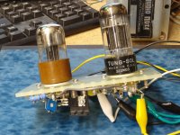
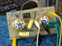
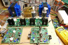
The test setup seen here in pictures #487 and 490 still exists but is being refitted with UNSET output boards for some high power amp experimentation. I have used this same pair of UDB's for several experiments with small (6V6GT, 6K6, 6W6) tubes and big sweeps like the 26HU5 and 6LW6. I'll create a parts list from these boards once I finish the PC build mess that has taken over the workbench.
The first iteration of the UDB was made on a turret board in 2007. I slapped it together so I could test some big sweep tubes in conventional G1 drive as well as screen (G2) drive applications where huge AC drive voltages are needed. Despite the obvious physical differences, both tubes were always 6SN7's. This thing went through several changes as the needs dictated and got used a lot. There was obviously at least one attempt at a PC board back in 2007 and KT88's were involved. 2007 and 2008 brought a lot of challenges with the death of my father and Sherri's stepfather, a bout with recurring aggressive skin cancer and a job change. The board sat on the bench unused a lot.
In 2008 I had begun to tinker with tubes again and a question was asked on diyAudio which got the board out of the box where unused boards go to be relieved of useful parts. That happened in post #94 in this thread which evolved into a Push Pull 6L6GC amp in Australia, and the UDB here over nearly 4 years.
In this thread Amp design suggestions Eli was suggesting a 6L6 AB2 design based on Mullard 5-20 topology with 12AT7 front end and ECC99 LTP and Mosfet source followers. Respecting the original thread, Eli asked to start this new one.
I am interested in progressing with this design, looking for any assistance 😉
Cheers,
Chris
I am interested in progressing with this design, looking for any assistance 😉
Cheers,
Chris
- chrish
- Replies: 689
- Forum: Tubes / Valves
By 2010 I could see that Motorola was on a long slow downsizing / offshoring of the plant where I worked, and tech in general was dying off in South Florida so plans were put in motion for my eventual retirement which did come far earlier than I expected. There were several road and air trips between South Florida and West Virginia with lots of down time due to health issues with relatives. I used that time to lay out PC boards on my laptop. I still have at least 20 completed or partially completed designs of several tube and solid state PC boards related to audio reproduction or music synthesizers on my hard drive. In 2013 I accepted a buyout offer from Motorola, which got delayed twice. I left Florida in July of 2014. We were in temporary housing for about a year while this house was being built so little electronics work occurred. I did take the best ideas from several versions of push pull driver boards, roll it all into one good board and sent it out to a board shop. The boards sat in the box for several months until I had a minimal workbench set up in the new house. Just as the push pull amp experiments got going full steam, I had to revisit the original TSE since Sharp had discontinued the filament regulator chip and a weasel bought up all of the remaining US stock. This upheaval caused some delay, but resulted in the TSE-II design which is larger and far less crowded than the original TSE which was really designed for 45 tubes. It uses a different filament regulator, but the same proven audio path on a larger board with improved thermal management.
Post # 630 in the 6L6-AB2 thread shows one of the current UD boards after I made a minimal change to replace some LED's with real voltage reference chips. The board has remained unchanged ever since, it just works. Unfortunately, during all of the often unscheduled movement lots of stuff got lost including a whole moving box full of documentation.
The test setup seen here in pictures #487 and 490 still exists but is being refitted with UNSET output boards for some high power amp experimentation. I have used this same pair of UDB's for several experiments with small (6V6GT, 6K6, 6W6) tubes and big sweeps like the 26HU5 and 6LW6. I'll create a parts list from these boards once I finish the PC build mess that has taken over the workbench.
Attachments


A few years ago I built up a UDB with one of George’s PCBs and used it for testing 6HJ5s in crazy-drive configuration. The UDB performed perfectly, but the crazy-drive distortion test results were very disappointing.
Sometime later I decided to replace the amplification, phase splitter and driver stages of the first 2 amps I built, 6550 Williamson’ish mono-blocks, with UDBs. I did some testing and the results were excellent so I made up my own PCBs in order to use the existing tube holes in the chassis, loaded and tested one. Then other projects (a 300B TSEII and a higher power Engineer’s Amp) put that on the back-burner.
Having now completed those 2 projects I’ve resurrected the Williamson amp UDB upgrade project.
I am trying to populate my boards bought last year.
I used this thread as reference:
I suppose I could create a spice model and compare the values, but was wondering if anyone has the definitive BOM?
Also, has anyone used anything that is not a 6CG7? They are not the most common option in Europe. ECC804 (6/30L2) looks similar on paper (mu 18 instead of 20) and I have those, but interested if anything else has been tried.
I used this thread as reference:
Tubelab Universal Driver Board, 2015 version
There are a lot of significant differences between the BOM on that thread and the one on this. E.g. R6/R7, 43K here, 150K on the other thread, R17/R18, 20K here, 68K on the other thread.I suppose I could create a spice model and compare the values, but was wondering if anyone has the definitive BOM?
Also, has anyone used anything that is not a 6CG7? They are not the most common option in Europe. ECC804 (6/30L2) looks similar on paper (mu 18 instead of 20) and I have those, but interested if anything else has been tried.
As noted in the BOM, selection of R6/R7 and R17/R18 will depend on HT and tube choice. Whether you're using anode to anode feedback (2nd stage to first stage or outputs to first or second stage) will have an impact too.
I did a lot of simulation and testing a few years ago. I ended up going with the original 150k and 24k with 500V HT and no anode to anode feedback. I have no problem using 12dB or so of GNFB.
I did some simulations with 6GU7s but the 6CG7s are easy to order online from the US so went with those.
I did a lot of simulation and testing a few years ago. I ended up going with the original 150k and 24k with 500V HT and no anode to anode feedback. I have no problem using 12dB or so of GNFB.
I did some simulations with 6GU7s but the 6CG7s are easy to order online from the US so went with those.
I should have read the disclaimer in the other thread ...
I need to look more closely at my project. I will be driving two UNSET Power Heads in PP, with 25CD6GB outputs.Here is the schematic for the not so new board. Being a "universal" board requires a different parts list for each application, and some parts are not used in each application. A generic parts list is done, but it had NOT been optimized for any specific application. Specific versions are coming soon.
Been there, built that.I need to look more closely at my project. I will be driving two UNSET Power Heads in PP, with 25CD6GB outputs.
Driving an UNSET Power Head in PP works great, but you will need to leave some parts off the driver board build. The UDB has a mosfet follower for driving the grid of the output tubes and providing adjustable bias. The UNSET Power Head (UPH) board also has a mosfet follower to drive the cathode of the output tubes with its own bias adjustment. You don't need both, and the cathode must be driven in UNSET, so the mosfet follower and associated parts can be omitted on the UDB build.
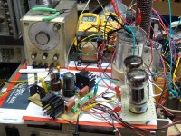
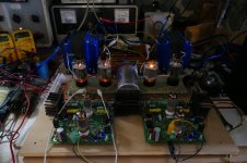
I have the setup seen in the picture still on the bench. Some parts like the OPT's and one driver board have been removed for some serious high power testing (over 500 watts from 4 X 26HU5's). I should be able to put one channel back together pretty quickly. I have lots of 25DN6 tubes here which are similar and have the same pinout. I probably have some 6CD6's in storage too.
If you tell me how much B+ you plan to run, and your OPT impedance, I can mock this up pretty quickly.
Attachments
Boy, I forgot I posted this but am glad I did. It is hard to spend a few hours on audio projects every few months ... especially when so many are in progress.As noted in the BOM, selection of R6/R7 and R17/R18 will depend on HT and tube choice. Whether you're using anode to anode feedback (2nd stage to first stage or outputs to first or second stage) will have an impact too.
I did a lot of simulation and testing a few years ago. I ended up going with the original 150k and 24k with 500V HT and no anode to anode feedback. I have no problem using 12dB or so of GNFB.
I did some simulations with 6GU7s but the 6CG7s are easy to order online from the US so went with those.
So, DH53, if I'm reading right, you mean you did 6550s per the BOM with 150k R6/R7 and 24k R17/R18 on 500V HT?
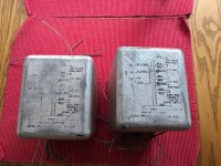
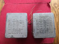
One of my potential plans is to use the iron set from Allen Organ 75s, which were 6550 amps with big Acro OPTs (3300ohm primaries, originally for 6550s).
The power supply for the original amps shows 455V, using the PTs into a SS full wave, choke input. But the primaries are 115V and 125V, and because my line tends to run 120ish or a little over, I'm thinking that an essentially the stock supply would put me around 475V (or a bit more, lighting fewer tubes), though potentially needing some caution on the filaments. I could buy new PTs, but it would seem a shame to split up the gang. (I have the chokes, too, though they aren't pictured.)
I asked about other options because this build seems a tad tame compared to what the UDP boards could do and I do love goofing with DHTs. But given my time constraints, it is nice to also have projects that are decently likely to work as initially conceived.
Paul
Attachments
Yes, I did use 6550s as per the BOM with 150k R6/R7 and 24k R17/R18 with 500V HT.
It sounds like your transformers will be fine. The additional 5V of mains voltage is only ~4.5%. That'll only be an additional 0.3V on a 6.3V secondary.
For a stock, standard 6550 amp the UDB is a bit of overkill but the performance will be very good and can be improved further with the plate-to-plate feedback options.
The UDB uses ±150V supplies for the MOSFETs. For a standard PP 6550 output stage even ±75V would be fine. The larger voltage swings are only needed for screen-driving output tubes or using cathode feedback in the outputs.
My version used +- 150 volts because it's easy to make from any low buck isolation transformer with a pair of 120 volt secondaries, or an N-68X hooked up backwards. The two supplies don't even need to be the same voltage. You just need enough negative voltage to completely cut the output tubes off and enough positive voltage to feed the voltage reference in the offset cancelling circuit. 5 volts or so will work if you are not driving the output tubes into positive grid territory. You will need enough positive voltage to drive whatever your output tubes need with a few volts of headroom if A2, AB2 or screen drive is used.The UDB uses ±150V supplies for the MOSFETs. For a standard PP 6550 output stage even ±75V would be fine.
Hoping for a nudge in the right direction.
I have decided that in order to be able to populate the UDB with confidence, I need to be able to simulate one of the BOM options so that I can adapt the board for my project.
Since @dch53 has a successful implementation, I used his BOM to build an LTSpice simulation.

Unfortunately I have run into a bit of a brick wall getting meaningful results. The first stage seems to be OK, but the output goes to pot.

I will continue to try to debug it, but f anyone can see my silly mistake I would be grateful for the help. ASC file in the attached zip.
I have decided that in order to be able to populate the UDB with confidence, I need to be able to simulate one of the BOM options so that I can adapt the board for my project.
Since @dch53 has a successful implementation, I used his BOM to build an LTSpice simulation.
Unfortunately I have run into a bit of a brick wall getting meaningful results. The first stage seems to be OK, but the output goes to pot.
I will continue to try to debug it, but f anyone can see my silly mistake I would be grateful for the help. ASC file in the attached zip.
Attachments
Hi. Nothing obvious catches my eye. Is the expected current flowing through the MOSFETs?
The advice I was given when I was in your situation, is to simplify the schematic - replace the CCSs with current sources, replace the bias with voltage sources, get rid of all the power supply capacitors and simply earth the non input side of the first long-tailed pair (omit the lamp).
You'll still be able to get useful information from the model, like distortion, power consumption of components, gain, power etc. The simulation will also run much faster.
Once you have that working you can add the bells and whistles back in.
One thing I will suggest, is that long-tailed pairs are usually drawn as George did in his original schematic. Maybe it's just me, but seeing them all sideways made it difficult for me to understand the schematic. Here for example is one of my models

Happy to send you one of my models if you'd like.
The advice I was given when I was in your situation, is to simplify the schematic - replace the CCSs with current sources, replace the bias with voltage sources, get rid of all the power supply capacitors and simply earth the non input side of the first long-tailed pair (omit the lamp).
You'll still be able to get useful information from the model, like distortion, power consumption of components, gain, power etc. The simulation will also run much faster.
Once you have that working you can add the bells and whistles back in.
One thing I will suggest, is that long-tailed pairs are usually drawn as George did in his original schematic. Maybe it's just me, but seeing them all sideways made it difficult for me to understand the schematic. Here for example is one of my models
Happy to send you one of my models if you'd like.
Hi @dch53 , a copy of your model would be very useful, thanks. I will pinch your potentiometer models for one thing!
I am trying to recall why I drew it the way I did. I think it was because on the original schematic (which was also describing the external connectivity on the PCB) there are a lot of bunched horizontal connections between the tubes, and I was struggling to see the circuit. Your interpretation is much clearer.
I am trying to recall why I drew it the way I did. I think it was because on the original schematic (which was also describing the external connectivity on the PCB) there are a lot of bunched horizontal connections between the tubes, and I was struggling to see the circuit. Your interpretation is much clearer.
- Home
- More Vendors...
- Tubelab
- Universal PP Driver Board Builds and BOMs?