Hello everyone,
I’m working on designing a Class H audio amplifier with a power output of 2000W RMS at 4Ω load, and I need some guidance from experienced designers.
I've previously designed a a 800W RMS Class AB amplifier for outdoor applications. Now, I want to develop a high-efficiency Class H amplifier for professional audio use.
✅ Topology: Class H with multiple rail switching
✅ High Efficiency & Low Distortion
✅ Stable Power Supply Design
✅ Thermal Management & Protection Circuits
I’d appreciate any insights on:
🔹 Proper rail voltage selection for efficient power switching
🔹 Best MOSFETs/BJTs for high power handling
🔹 Reliable protection circuits (Overcurrent, DC, thermal, SOA protection)
🔹 PCB layout guidelines to minimize noise and EMI
🔹 Any reference schematics, simulations, or design resources
If you have experience in designing high-power Class H amplifiers, I’d love to hear your advice! Feel free to drop suggestions, references, or even share your past projects.
Thanks in advance! 😊🎛️🔊
I’m working on designing a Class H audio amplifier with a power output of 2000W RMS at 4Ω load, and I need some guidance from experienced designers.
I've previously designed a a 800W RMS Class AB amplifier for outdoor applications. Now, I want to develop a high-efficiency Class H amplifier for professional audio use.
Key Requirements:
✅ Output Power: 2000W RMS @ 4Ω✅ Topology: Class H with multiple rail switching
✅ High Efficiency & Low Distortion
✅ Stable Power Supply Design
✅ Thermal Management & Protection Circuits
I’d appreciate any insights on:
🔹 Proper rail voltage selection for efficient power switching
🔹 Best MOSFETs/BJTs for high power handling
🔹 Reliable protection circuits (Overcurrent, DC, thermal, SOA protection)
🔹 PCB layout guidelines to minimize noise and EMI
🔹 Any reference schematics, simulations, or design resources
If you have experience in designing high-power Class H amplifiers, I’d love to hear your advice! Feel free to drop suggestions, references, or even share your past projects.
Thanks in advance! 😊🎛️🔊
Output power - requires a +/-165 V supply, with 2.5-3kVA of toroid. If you want a SMPS, you will need more expertise than I have. I don’t know if Eva is still around…. S/he is your best resource here.
Multiple rails - at least 3 step. One I’m (still) working on is 4, on +/-165V. I had a lower voltage prototype working well on +/-140, 3-step. The unit just didn’t lend itself to road use - but bench tested fine.
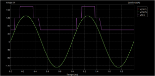
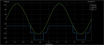
High efficiency - won’t be class D efficient, but still power savings over class AB is dramatic. Even going from 2 to 3 steps is a huge boost in efficiency at normal music levels. The boost becomes less as you push it to war volume, because that’s when 2 step is at its best. 2 step is HORRIBLE if you are using active limiting ahead of the amplifier (to protect speakers). It can never approach full output but is being constantly driven hard enough to switch to the high rail. Not a good combination. The more steps you have the better off you are when using active limiting.
Low distortion - expect about .03-.05%, even if you had infinite feedback. Limited by internally generated EMI and commutation noise. No one will ever notice this in operation, for the intended uses.
Stable power supply design - see the first bullet. You plug a toriodal supply in and it works. Overload it by a factor of 4 for an hour and it just runs a little warm. And your mains breaker eventually trips Overload it by a factor of 10 and it just drops to 65% of no-load. And your mains breaker trips in two or three seconds. If you start designing a switch mode supply that can do this without complaint, you MIGHT be done by the time Zefram Cochrane launches his first warp driven ship (2063). You will have a bucket full of blown IGBTs and three or four discharged fire extinguishers to show for it in the meantime. The amplifier itself is trivial by comparison.
Thermal management and protection or circuits - will comprise well over half the actual electronics. None of it is THAT hard to do. But each little block has to be thoroughly vetted. One I did had four levels of thermal control. Step one turned the fan on high. Step two enforced the clip limiting circuits, even if they were disengaged. Step three mutes the affected channel, switching out of bridge mode if one side runs hot and the other not as hot yet. Can run at reduced output. Step four kills power and latches it off, requiring a manual restart.
Best BJTs to use - there is only one logical choice, MJL21193/4. Do not use mosfet output transistors at this power level or attempt to use 2SC5200’s. Mosfet switches are required - look for 5 milliohms or less, in TO-247. 60 or75V types are all thats needed. Types offered for sale change almost daily. You might not be able to buy the same ones twice.
Layout guidelines - keep the power switching at the opposite end from the audio stage. Use a pair of clamshell heat sinks which put the inputs next to each other. Put all the supervisor/protection on a daughter board - you may be able to share it between two channels.
Reference schematics - there are pieces all over the place, but one master you could just copy is a tall order. None of mine are exact copies - they use the best pieces from several different places. My old +/-140V prototype used an amplifier circuit resembling the old BGW with custom VI limiters and QSC’s rail switches. The bridging adapter and limiters came out of the PLX series, with some minor mods. But the thermal management was all new. Toroids were custom wound by me on Toroid Corp prewound primary kits.
I’ve been working with these things for years and gotten many versions up and running. But have NOT been able to construct one that’s truly road-worthy. Sure, they’ll turn the speaker to charcoal long before it cries uncle, but one dropped on the floor from three feet is a goner.
Multiple rails - at least 3 step. One I’m (still) working on is 4, on +/-165V. I had a lower voltage prototype working well on +/-140, 3-step. The unit just didn’t lend itself to road use - but bench tested fine.
High efficiency - won’t be class D efficient, but still power savings over class AB is dramatic. Even going from 2 to 3 steps is a huge boost in efficiency at normal music levels. The boost becomes less as you push it to war volume, because that’s when 2 step is at its best. 2 step is HORRIBLE if you are using active limiting ahead of the amplifier (to protect speakers). It can never approach full output but is being constantly driven hard enough to switch to the high rail. Not a good combination. The more steps you have the better off you are when using active limiting.
Low distortion - expect about .03-.05%, even if you had infinite feedback. Limited by internally generated EMI and commutation noise. No one will ever notice this in operation, for the intended uses.
Stable power supply design - see the first bullet. You plug a toriodal supply in and it works. Overload it by a factor of 4 for an hour and it just runs a little warm. And your mains breaker eventually trips Overload it by a factor of 10 and it just drops to 65% of no-load. And your mains breaker trips in two or three seconds. If you start designing a switch mode supply that can do this without complaint, you MIGHT be done by the time Zefram Cochrane launches his first warp driven ship (2063). You will have a bucket full of blown IGBTs and three or four discharged fire extinguishers to show for it in the meantime. The amplifier itself is trivial by comparison.
Thermal management and protection or circuits - will comprise well over half the actual electronics. None of it is THAT hard to do. But each little block has to be thoroughly vetted. One I did had four levels of thermal control. Step one turned the fan on high. Step two enforced the clip limiting circuits, even if they were disengaged. Step three mutes the affected channel, switching out of bridge mode if one side runs hot and the other not as hot yet. Can run at reduced output. Step four kills power and latches it off, requiring a manual restart.
Best BJTs to use - there is only one logical choice, MJL21193/4. Do not use mosfet output transistors at this power level or attempt to use 2SC5200’s. Mosfet switches are required - look for 5 milliohms or less, in TO-247. 60 or75V types are all thats needed. Types offered for sale change almost daily. You might not be able to buy the same ones twice.
Layout guidelines - keep the power switching at the opposite end from the audio stage. Use a pair of clamshell heat sinks which put the inputs next to each other. Put all the supervisor/protection on a daughter board - you may be able to share it between two channels.
Reference schematics - there are pieces all over the place, but one master you could just copy is a tall order. None of mine are exact copies - they use the best pieces from several different places. My old +/-140V prototype used an amplifier circuit resembling the old BGW with custom VI limiters and QSC’s rail switches. The bridging adapter and limiters came out of the PLX series, with some minor mods. But the thermal management was all new. Toroids were custom wound by me on Toroid Corp prewound primary kits.
I’ve been working with these things for years and gotten many versions up and running. But have NOT been able to construct one that’s truly road-worthy. Sure, they’ll turn the speaker to charcoal long before it cries uncle, but one dropped on the floor from three feet is a goner.

Just curious. What I do not understand is why you need this amount of power? It’s not like a single speaker can handle it or if it is being spread out over multiple speakers in a series/parallel arrangement? I would think multiple 800W amps would be a better solution.
They are used when you need multiple 2000+ watt amps. A 2000 watt amplifier channel is about right for driving a single 18 with a 4 inch coil or two 12” midranges. Music festival or rave use requires more than this, unless you enjoy reconing blown speakers trying to use a rig that’s too SMALL. One of the biggest challenges to making an amp like this is making it manufacturable - that is, to be able to make half a dozen of them easily and repeatably. That is still WIP on my end. The end goal being to replace every store bought amp in my big rig with a DIY creation. The CA18’s are a tough nut to crack, but I’m convinced I can make one better suited with 4 step class H instead of only 2. Remember what I said about using them with limiters (makes them run HOT). You do want peak power to be very high but long term to be limited to the thermal limits of the VC (about 500 watts).
I know, I know you are just supposed to hire it all out when you want to do something like this, but some people might get a bug up their butt and actually want to build their own rig. I could also go buy 20 pound class D, at $5000+ a pop. Those also don’t like it when driven to FULL power for 5 or 10 seconds. Headroom use only at those levels, so you move up to the $15000 models to get equivalent capacity. And of course since mentioned a half dozen…..
I know, I know you are just supposed to hire it all out when you want to do something like this, but some people might get a bug up their butt and actually want to build their own rig. I could also go buy 20 pound class D, at $5000+ a pop. Those also don’t like it when driven to FULL power for 5 or 10 seconds. Headroom use only at those levels, so you move up to the $15000 models to get equivalent capacity. And of course since mentioned a half dozen…..
The lighting is supposed to be on a separate distro. Even with much smaller rigs. Even my little DJ rig (5.9 kW, one of those big amps, and two smaller ones) needs the bass on one leg of 120/240 and everything else on the other. And another similar distro for the lights, plugged in remotely. Since relamping with LED it’s current consumption has gone way down - but I still don’t want sound taking out the lights or vice versa.
Thank you for this detailOutput power - requires a +/-165 V supply, with 2.5-3kVA of toroid. If you want a SMPS, you will need more expertise than I have. I don’t know if Eva is still around…. S/he is your best resource here.
Multiple rails - at least 3 step. One I’m (still) working on is 4, on +/-165V. I had a lower voltage prototype working well on +/-140, 3-step. The unit just didn’t lend itself to road use - but bench tested fine.
High efficiency - won’t be class D efficient, but still power savings over class AB is dramatic. Even going from 2 to 3 steps is a huge boost in efficiency at normal music levels. The boost becomes less as you push it to war volume, because that’s when 2 step is at its best. 2 step is HORRIBLE if you are using active limiting ahead of the amplifier (to protect speakers). It can never approach full output but is being constantly driven hard enough to switch to the high rail. Not a good combination. The more steps you have the better off you are when using active limiting.
Low distortion - expect about .03-.05%, even if you had infinite feedback. Limited by internally generated EMI and commutation noise. No one will ever notice this in operation, for the intended uses.
Stable power supply design - see the first bullet. You plug a toriodal supply in and it works. Overload it by a factor of 4 for an hour and it just runs a little warm. And your mains breaker eventually trips Overload it by a factor of 10 and it just drops to 65% of no-load. And your mains breaker trips in two or three seconds. If you start designing a switch mode supply that can do this without complaint, you MIGHT be done by the time Zefram Cochrane launches his first warp driven ship (2063). You will have a bucket full of blown IGBTs and three or four discharged fire extinguishers to show for it in the meantime. The amplifier itself is trivial by comparison.
Thermal management and protection or circuits - will comprise well over half the actual electronics. None of it is THAT hard to do. But each little block has to be thoroughly vetted. One I did had four levels of thermal control. Step one turned the fan on high. Step two enforced the clip limiting circuits, even if they were disengaged. Step three mutes the affected channel, switching out of bridge mode if one side runs hot and the other not as hot yet. Can run at reduced output. Step four kills power and latches it off, requiring a manual restart.
Best BJTs to use - there is only one logical choice, MJL21193/4. Do not use mosfet output transistors at this power level or attempt to use 2SC5200’s. Mosfet switches are required - look for 5 milliohms or less, in TO-247. 60 or75V types are all thats needed. Types offered for sale change almost daily. You might not be able to buy the same ones twice.
Layout guidelines - keep the power switching at the opposite end from the audio stage. Use a pair of clamshell heat sinks which put the inputs next to each other. Put all the supervisor/protection on a daughter board - you may be able to share it between two channels.
Reference schematics - there are pieces all over the place, but one master you could just copy is a tall order. None of mine are exact copies - they use the best pieces from several different places. My old +/-140V prototype used an amplifier circuit resembling the old BGW with custom VI limiters and QSC’s rail switches. The bridging adapter and limiters came out of the PLX series, with some minor mods. But the thermal management was all new. Toroids were custom wound by me on Toroid Corp prewound primary kits.
I’ve been working with these things for years and gotten many versions up and running. But have NOT been able to construct one that’s truly road-worthy. Sure, they’ll turn the speaker to charcoal long before it cries uncle, but one dropped on the floor from three feet is a goner.
few questions ,,,
Can u share the schematic of your 3 tier class h prototype ? what about its output power , THD , Gain , Damping factor ?
And should I directly make the 2000watt or I should start with lower power class H like 200w or 500 watt ?
I have a torroidal transformer of class H amp ,,, with 2 different supplies 50-0-50 and 100-0-100 , I want to use it for future testing of class H prototypes
800w is suitable for small events or for lower power speakers but for 18 inches woofers we need high power amps like 2000w,4000w or moreJust curious. What I do not understand is why you need this amount of power? It’s not like a single speaker can handle it or if it is being spread out over multiple speakers in a series/parallel arrangement? I would think multiple 800W amps would be a better solution.
It’s not necessarily the diaphragm inches, its the voice coil inches and Xmax. Mine just happen to be 18TBW100’s, and 2K-ish watts just happens to be the right amount of power. The 21’s and 18’s with the 6” coils can eat more - especially the ones with 20 mm of throw. The big boys will make 16 and 32 element arrays out of the damn things.
The 3 tier did just under 1400 wpc. I don’t think there is a full schematic for it - it is literally pieces. It’s an amp that I’ve used before with rail switches added, with a daughterboard for the preamp and supervisor circuits, which were developed separately. I can probably dig up the pieces. I never actually measured distortion on it, but the old +/-127V class AB cascode output amp that it was based on did about .02% at 20k. And melted the plugs off the extension cords one 4th of July evening. I was running lab horns with them at a fireworks show. THAT convinced me I had to go to H class to do any real gigs with. I bought some used CA18’s that were retired from touring.
The 3 tier did just under 1400 wpc. I don’t think there is a full schematic for it - it is literally pieces. It’s an amp that I’ve used before with rail switches added, with a daughterboard for the preamp and supervisor circuits, which were developed separately. I can probably dig up the pieces. I never actually measured distortion on it, but the old +/-127V class AB cascode output amp that it was based on did about .02% at 20k. And melted the plugs off the extension cords one 4th of July evening. I was running lab horns with them at a fireworks show. THAT convinced me I had to go to H class to do any real gigs with. I bought some used CA18’s that were retired from touring.
Hi, I did look at some high power speaker specs, wow a lot of juice. Why not use a bridge amp configuration for a 2kW woofer? Active cross over and a separate amp for the highs?
Sometimes we do bridge them, and push 4-5 kW per woofer. Smaller rigs with only say 1 pair of 18’s just bridge a single smaller amp. But when you start doing bigger rigs you get bigger amps, and keep all the smaller ones (say, 800-1200 per channel) to run midranges.
Always separate amps for the subs, kick bins (if used) and mid/tops. And the mid/tops can further be bi-ampd.
When you move up into true large format PA, normal professional advice is NEVER to bridge amplifiers. Makes them run too hard for day in day out road use. The modern switching amps can get HUGE, although their RMS ratings are really just a “burst” rating for a few milliseconds at a time. Same can be said for iron pigs, although the length of the burst is only limited by the AC mains breaker and long term (5+ minutes) limited by heat sinking. Smaller bridged amplifiers can also have their transformer overheat, while the bigger one using 2-3 kVA toroid will outlast a 20A/120V mains breaker.
but i don't know where to start ,i need a good circuit for referenceIt’s not necessarily the diaphragm inches, its the voice coil inches and Xmax. Mine just happen to be 18TBW100’s, and 2K-ish watts just happens to be the right amount of power. The 21’s and 18’s with the 6” coils can eat more - especially the ones with 20 mm of throw. The big boys will make 16 and 32 element arrays out of the damn things.
The 3 tier did just under 1400 wpc. I don’t think there is a full schematic for it - it is literally pieces. It’s an amp that I’ve used before with rail switches added, with a daughterboard for the preamp and supervisor circuits, which were developed separately. I can probably dig up the pieces. I never actually measured distortion on it, but the old +/-127V class AB cascode output amp that it was based on did about .02% at 20k. And melted the plugs off the extension cords one 4th of July evening. I was running lab horns with them at a fireworks show. THAT convinced me I had to go to H class to do any real gigs with. I bought some used CA18’s that were retired from touring.
I’ll see if I can get some good legible pictures off the screen of my CAD computer this evening. It literally cannot talk to the machines I use for entertainment, which this qualifies as. Neither can my financial computer. The air gap is the only true security measure, unfortunately, unless I throw continuous money at the problem. Even then, s*** happens. I’d rather put more money into more transformers, rather than some stupid subscription-based security solution. Paranoid? Damn right. Cheapskate? That too.
If you think developing 5 kWin class H is a b****, try it in class D. You’ll be ready for the funny farm. In order for switching amplifiers to work reliably, they need to be “electrically small” compared to the wavelengths involved. The required edge speeds for class D correspond to very high frequencies, hence short wavelengths. A bank of switching transistors 10 or 15 inches long simply won’t work reliably. Class H requires no more than a 20 KHZ switching frequency, and typically much lower. Slowing the edge rate down to a microsecond isn’t the end of the world. Do that in class D with 200kHz switching and efficiency goes right into the toilet. A single TO-220 will switch plenty fast enough, but just try pushing those currents through the PCB traces with a 0.1” pin pitch.
Not saying that it can’t be done but the required development efforts are infinitely harder. The OP was asking for reference schematics. If that’s his level of expertise, doing 5KW class D is WAY beyond him. There is a reason those amplifiers run $5k-$15k.
Not saying that it can’t be done but the required development efforts are infinitely harder. The OP was asking for reference schematics. If that’s his level of expertise, doing 5KW class D is WAY beyond him. There is a reason those amplifiers run $5k-$15k.
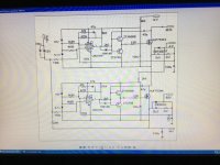
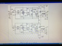
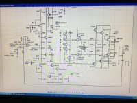
I’ll see if I can get some good legible pictures off the screen of my CAD computer this evening.
This is the audio section from the 3 tier. The amp itself is not really that complicated. Only one pair of outputs is shown, but it uses nine pairs, plus the drivers. Preamp and protection stuff is on another board.
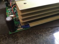
The only full module pic I have right now isn’t a very good one. I’ll see if it’s possible to unpack easily, and get something better.
Attachments
- Home
- Amplifiers
- Solid State
- Seeking Help in Designing a Hi-Fi Class H Amplifier (2000W RMS @ 4Ω Load)