Hi everyone,
I want to make low DCR 10mH and 8.2mH inductors similar to Jensen c core or Torobar, using a laminated steel toroid core. I noticed that Jensen uses a single-piece strip and does not completely cut the core to create an air gap.
How can I apply a similar air gap without fully cutting the core? What’s the best method to achieve this?
Thanks!
Hello!
This is an interesting topic.
Why do you prefer a toroid instead of an E-I?
E-I you can easily control the gap and it is much simpler to make the winding.
How much effective permeability (relatively to the air core) do you plan to use?
In my experiments, I see that between 10 an 15 the THD is low (<0.3% maximum measurement resolution I used).

Hi. With toroidal construction there will be lower DCR. And lower power loss.
Producer told EI cores with airgap can not be oriented grain. I don't know how to make air gap for both of them. Can you please draw ? Regards
Producer told EI cores with airgap can not be oriented grain. I don't know how to make air gap for both of them. Can you please draw ? Regards
Hi,
I use an E and an I as shown in the picture. I pack all the E's and all the I's separately.
In a transformer E and I are interlaced and packed together since you don't want any gap.
But for inductors, you want the gaps.
Between the E and the I, I insert some material (used x-ray film for example) to provide the spacing and by this way, I adjust how much gap I need.
I use laminated steel used in regular 60Hz transformers.
If I want a 5mH, I build an air core of 300 to 500uH and adjust the gap to achive from 10 to 15 times the inductance.
The less you multiply, the more linear your inductor you be, but bigger it will be.
Between 10 and 15, I think you get a good balance between gain and THD (this is my experience only).
I think there might be a misunderstanding on the one of their products dealer seller’s page, or perhaps I am misinterpreting something. They describe their inductor core as follows:
"The core is formed like a donut with a round cross-section, and it is wound from one long piece of laminated steel tape."
This confuses me because it suggests that the core is made from a single continuous strip of laminated steel, without any cuts. However, I thought that they introduce an air gap by drilling holes in the core every 10 cm or so.But not cutting the sheets completely.
My question is: How exactly do they achieve an air gap in such inductors?
If the core is truly wound from one continuous strip, does drilling holes effectively create an air gap?
Wouldn’t the magnetic flux simply bypass the holes, minimizing their impact?
Or is there another method they use to introduce an air gap while keeping the core as a single piece?
I’d love to hear insights from those with experience in this type of inductor design!
Hi @Veysel - Sounds like a cool project, but keep in mind that low DCR is not always the goal. Several times I've picked a specific gauge of inductor to have a specific amount of DCR.
Inductors often are a good place to add resistance since they tend to have very good power handling. Two areas where this is beneficial is in a baffle step compensation circuit as well as even order filter components which need a little R in series to keep the overall impedance from taking a nose dive. Having a crossover simulator like XSim or VituixCAD can really help.
I look forward to seeing what you accomplish.
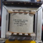
Hello.
On the dealer’s website, it states that the C-Coil cannot be measured with standard LCR meters. Here is the note:
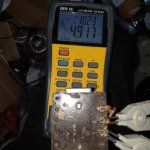
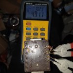
My Der EE DE-5000 LCR meter can measure inductances as high as 5H. I’ve attached a picture as proof. Could this note be referring to typical LCR meters with lower measurement capabilities?
Additionally, can these C-Core inductors be used in passive amplifiers like the Pass F5? Would they be suitable for a CLC power supply? Also, are gapped or non-gapped inductors better for a CLC filter in Class A amplifiers?
Regards
On the dealer’s website, it states that the C-Coil cannot be measured with standard LCR meters. Here is the note:
Please note!
The C-Coil cannot be measured using a universal LC meter. Due to the characteristics of the core and winding method, it is important to use a professional RLC meter. We measure all C-Coils before shipping them using a professional RCL meter at AC 1V, 1kHz.
The C-Coil is not recommended for any other use than in passive loudspeaker crossovers due to the toroidal core’s strong electromagnetic output. These coils are not suitable for use in amplifiers or active systems.
My Der EE DE-5000 LCR meter can measure inductances as high as 5H. I’ve attached a picture as proof. Could this note be referring to typical LCR meters with lower measurement capabilities?
Additionally, can these C-Core inductors be used in passive amplifiers like the Pass F5? Would they be suitable for a CLC power supply? Also, are gapped or non-gapped inductors better for a CLC filter in Class A amplifiers?
Regards
Attachments
Regarding how to measure, what I've noticed is that when you measure iron core coils with an equipament that injects a very small current (3mA in my multimeter for example) the result is a lower inductance. As an example, a 5mH iron core inductor, if measured with my multimeter, shows 4mH.
Maybe the vendor mentions the especial equipment due to this fact.
In order to measure with higher current and also check the saturation max current, I apply a step voltage and take the curve current x time in the scope and then, calculate the using the formula V=L (di/dt) or L=V*(dt/di).
Note the knee in the curve when current exceeds 15A - this is when saturation occurs.
In this case, this inductor was for a 200W maximum @ 4ohms, which requires only 10Apeak max.
- Home
- Loudspeakers
- Multi-Way
- Low DCR toroidal steel inductor