Hello, a year ago I made a post where we tried to diagnose this amplifier without much success. Since then I have gained a little bit more knowledge and an oscilloscope.
Recap of what has happened:
Amplifier suddenly started going into protect, we suspect a loose battery terminal was the cause.
One IRFB7437 MOSFET was shorted (no idea if PSU side or output side, compact amplifier so I can't easily tell)
The driver 27324 also was dead and a resistor on its VDD. Also a few gate resistors were burned up.
After replacing the FET, driver and resistors, it just killed a different FET (because PSU was a battery, aka no current limit)
Middle pin of rectifiers is disconnected.
Info and equipment:
I will be able to diagnose more only during weekends.
PSU is a 12v 5A adapter, but can shut off due to overcurrent around 7-8A.
Multimeter Lovrum T28B
Oscilloscope ZEEWEI DSO1C81
Soldering iron
Current issue:
There was a bad solder joint on the driver, fixed that and now it seems to power on and go into protect properly, without being interrupted by the PSU shutting off, but some component is making a whining noise
The whining noise in question:
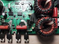
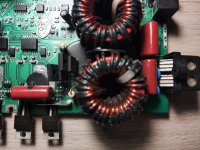
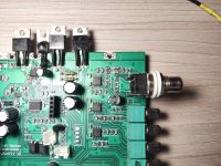
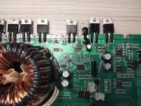
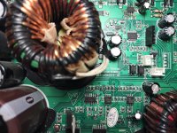
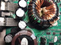
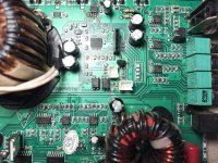
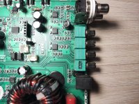
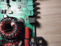
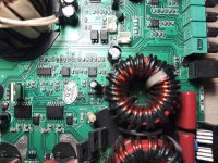
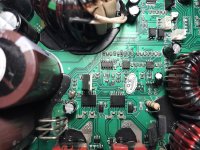
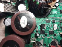
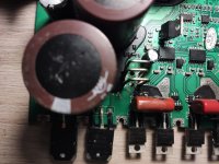
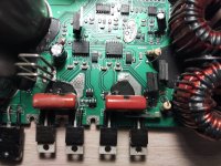
Board pics in attachments.
Measurements:
All gate resistors in spec ~4.7ohm
27524 driver: Works, all gates get a solid 25khz square wave
IRFB7437 (same on all of them, scope negative on ground):
Gate:
Drain:
Source: Nothing
I assume it's just the scope bugging out on the Gate measurement.
IRFB4321: nothing, I assume that's the output side which doesn't work because rectifiers middle pin is disconnected.
There is a blown up resistor in the middle of the board, unsure of its function, my guess would be a bleeder resistor, but there is a 2nd one intact.
Recap of what has happened:
Amplifier suddenly started going into protect, we suspect a loose battery terminal was the cause.
One IRFB7437 MOSFET was shorted (no idea if PSU side or output side, compact amplifier so I can't easily tell)
The driver 27324 also was dead and a resistor on its VDD. Also a few gate resistors were burned up.
After replacing the FET, driver and resistors, it just killed a different FET (because PSU was a battery, aka no current limit)
Middle pin of rectifiers is disconnected.
Info and equipment:
I will be able to diagnose more only during weekends.
PSU is a 12v 5A adapter, but can shut off due to overcurrent around 7-8A.
Multimeter Lovrum T28B
Oscilloscope ZEEWEI DSO1C81
Soldering iron
Current issue:
There was a bad solder joint on the driver, fixed that and now it seems to power on and go into protect properly, without being interrupted by the PSU shutting off, but some component is making a whining noise
The whining noise in question:
Board pics in attachments.
Measurements:
All gate resistors in spec ~4.7ohm
27524 driver: Works, all gates get a solid 25khz square wave
IRFB7437 (same on all of them, scope negative on ground):
Gate:
Drain:
Source: Nothing
I assume it's just the scope bugging out on the Gate measurement.
IRFB4321: nothing, I assume that's the output side which doesn't work because rectifiers middle pin is disconnected.
There is a blown up resistor in the middle of the board, unsure of its function, my guess would be a bleeder resistor, but there is a 2nd one intact.
Attachments
-
 1739651773458.jpg598.5 KB · Views: 57
 -
 1739651773463.jpg542.7 KB · Views: 51
 -
 1739651773353.jpg806.2 KB · Views: 51
 -
 1739651773360.jpg588.7 KB · Views: 49
 -
 1739651773357.jpg690.1 KB · Views: 47
 -
 1739651773371.jpg597.5 KB · Views: 49
 -
 1739651773366.jpg564.4 KB · Views: 49
 -
 1739651773378.jpg751.4 KB · Views: 49
 -
 1739651773385.jpg722.5 KB · Views: 55
 -
 1739651773390.jpg615.6 KB · Views: 49
 -
 1739651773396.jpg697.7 KB · Views: 47
 -
 1739651773402.jpg664.8 KB · Views: 52
 -
 1739651773408.jpg557.8 KB · Views: 54
 -
 1739651773437.jpg508.7 KB · Views: 52
 -
 1739651773449.jpg539.7 KB · Views: 58

That's just a snubber circuit. Not critical for operation.
Does it make that noise with the rectifiers in the circuit?
What do you mean by this statement:
go into protect properly
Posting the link to the other thread:
What caused the snubber resistor fail between the lats thread and now? Or did it simply get broken from impact?
Does it make that noise with the rectifiers in the circuit?
What do you mean by this statement:
go into protect properly
Posting the link to the other thread:
Hello, repairing my brothers PSP3500.1D (or trying to). Issue in the title.
Tools I have: Multimeter (has diode mode, beep, etc), soldering iron
How it happened: He was listening to music at a low volume, shut off the car and went to the shops, when he came back the amp was dead.
What I've done: Opened it up, found a IRFB7437 with the drain leg melted (see image below). Its 4.7ohm (4R7) gate resistor also was dead. Replaced both, still goes into protect.

Diagnostics:
There is no short between the RCAs and speaker outputs
There is an increasing resistance (goes from ~0 to...
Tools I have: Multimeter (has diode mode, beep, etc), soldering iron
How it happened: He was listening to music at a low volume, shut off the car and went to the shops, when he came back the amp was dead.
What I've done: Opened it up, found a IRFB7437 with the drain leg melted (see image below). Its 4.7ohm (4R7) gate resistor also was dead. Replaced both, still goes into protect.
Diagnostics:
There is no short between the RCAs and speaker outputs
There is an increasing resistance (goes from ~0 to...
- LatvianVideo
- Replies: 74
- Forum: Car Audio
What caused the snubber resistor fail between the lats thread and now? Or did it simply get broken from impact?
Last edited:
The rectifiers middle pin is disconnected, havent tried fully removing them or connecting the middle pin. In about 11 hours i can test different configurations of the rectifier
Previously when there was a bad solder joint on the driver, it made the psu shut off due to overcurrent, now it doesnt do that anymore and the amp can go into protect mode without any voltage drop on the psu, stays at a solid 12.1v.
I dont know what caused the snubber resistor to fail sadly.
Previously when there was a bad solder joint on the driver, it made the psu shut off due to overcurrent, now it doesnt do that anymore and the amp can go into protect mode without any voltage drop on the psu, stays at a solid 12.1v.
I dont know what caused the snubber resistor to fail sadly.
Last edited:
Does this amp have any sort of LED blink code to give an indication of the reason it's in protect?
Do you have a mains incandescent lamp or some other limiter (large 4 ohm resistor, like those for dummy loads) that you could insert with the output of one of the rectifiers to see if that would allow the amp to power up enough to troubleshoot more?
Do you have a mains incandescent lamp or some other limiter (large 4 ohm resistor, like those for dummy loads) that you could insert with the output of one of the rectifiers to see if that would allow the amp to power up enough to troubleshoot more?
It just constantly blinks power and protect LEDs
I don't have any limiter I could use to connect the rectifier to the board.
I guess the most obvious thing to do will be finding what's making that noise, possibly that has something to do with it going into protect.
I don't have any limiter I could use to connect the rectifier to the board.
I guess the most obvious thing to do will be finding what's making that noise, possibly that has something to do with it going into protect.
Some regulator circuits become unstable (do strange things) when their connection to the rail voltage is broken (rectifiers out of the circuit).
You don't have any dummy loads or any other large resistors?
No incandescent lamps in any small table lamps or anything else? Halogen work lights?
You don't have any dummy loads or any other large resistors?
No incandescent lamps in any small table lamps or anything else? Halogen work lights?
I remembered that cars have lights that could work for this. Right now I'm going to sleep, in the morning I'll take one and hook it up
Found an mains incandescent lamp, DC resistance about 87 ohms
Connected it between the middle pin and the board, but on the middle pin of the rectifier I connected, oscilloscope didn't read anything, but on the other rectifier (middle pin still disconnected from the board) it got a reading
FMG33R connected (probe on FMG33S middle pin):
FMG33S connected (probe on FMG33R middle pin):
Still whines and goes into protect.
Connect the negative rectifier normally and install the lamp between the output of the positive rectifier and the board.
Connected FMG33S normally, connected lightbulb to the FMG33R.
FMG33S middle pin doesn't read anything
FMG33R middle pin:
Still whines and goes into protect.
FMG33S middle pin doesn't read anything
FMG33R middle pin:
Still whines and goes into protect.
Noticed I did it the other way 🙂
now it's:
Connected FMG33R normally, connected lightbulb to the FMG33S.
FMG33R middle pin doesn't read anything
FMG33S middle pin:
now it's:
Connected FMG33R normally, connected lightbulb to the FMG33S.
FMG33R middle pin doesn't read anything
FMG33S middle pin:
As it tries to power up, do you see anything change on the output terminals of the two 2010 driver ICs? Any oscillation, any DCV build?
What's the DCV across the VSS and VDD terminals as it tries to power up?
DCV across the COM and VCC as it tries to power up?
Are you sure that all output FETs are 100% OK?
What's the DCV across the VSS and VDD terminals as it tries to power up?
DCV across the COM and VCC as it tries to power up?
Are you sure that all output FETs are 100% OK?
Some DC buildup and almost some oscillation on HO:
Similar on LO, but without DC:
Logic inputs HIN and LIN seem to be the same and look like this:
5v across VSS and VDD
12v across COM and VCC
5.5v between battery ground and SD (shutdown, I assume high is on)
Output FETs legs aren't shorted to eachother, so they should be good.
All measured with the rectifier connected using the lightbulb
- Home
- General Interest
- Car Audio
- GAS PSP3500.1D repair