My preamp has a jack (18v) on the back meant to power external devices. The manual states they placed a 1kohm resistor in series, and that the output will drop 1V for every 1ma drawn. I understand the math. But is the 1kohm resistor really needed, who are these underwriting organizations?
Can I put a jumper across the R94 (1Kohm) to make this all "standard" regulator circuit? I'd like to power some low voltage/low current devices from it to save on wallwarts.
Thanks!
The manual says:

Can I put a jumper across the R94 (1Kohm) to make this all "standard" regulator circuit? I'd like to power some low voltage/low current devices from it to save on wallwarts.
Thanks!
The manual says:
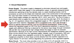
This jack, located below the Unswitched AC power outlets, supplies a regulated DC voltage which can be used to power cer- tain accessory devices which are designed for such a supply. The DC current is fed to the jack through a 1000 ohm resistor required by underwriting organizations, so the voltage supplied to an accessory will be reduced by 1 volt for each milliampere of current drawn by the accessory; thus if an accessory draws 3mA, the actual volt- age at the jack will be 18-3= 15 volts DC.
That restriction seems pretty strange to me. After all, you can purchase all kinds of power supplies, locally or online, that are capable of outputting much higher voltages and currents. I think that preamp vendor is being overly cautious.
18V via 1k won't power anything useful so it seems to me this output has another use such as a trigger for something.
If you link the resistor out you need to be aware of the max current you can draw and that is an unknown because we don't know the current draw of the internal circuitry, the heatsinking the 18v reg already has and the current ability of the unregulated side. In practice that means a current draw of more than say 100ma may start to be getting to much. I would probably add something like an ICP (integrated circuit protector... a fuse that looks like a TO92 transistor) of say T100ma.
If you link the resistor out you need to be aware of the max current you can draw and that is an unknown because we don't know the current draw of the internal circuitry, the heatsinking the 18v reg already has and the current ability of the unregulated side. In practice that means a current draw of more than say 100ma may start to be getting to much. I would probably add something like an ICP (integrated circuit protector... a fuse that looks like a TO92 transistor) of say T100ma.
The question is of course what type and brand preamp that is. Why? Because it is s specific question counting for a specific device. I smell the smell of something glowing as such odd stuff is usual found there.
It is quite unusual to have a higher output impedance with a regulator. It is then not a stable regulated voltage but merely an auxiliary voltage maybe to trigger something?! The schematic also shows the 7818 feeds other sectors of the device, possibly the manufacturer did not want complaining customers (the "underwriting organizations") that connect a toaster to the 18V output?! Overcurrent would have direct impact on the other sectors fed by that 7818.
To answer your specific question one needs to know the specific power draw of the device you want to connect and what power the transformer of that preamp can deliver. You see in our world things are calculated so we need details. Also not many devices can be fed with 18V and dropping voltage means much unnecessary heat. I see a situation occurring where you add a second tiny 7V 7VA toroid with tiny 5V regulated PSU connected to that DC jack for let's say a 5V 0.5A DAC.
The idea is good!
Last edited:
It's an Apt Holman preamp. The designers seem to be very meticulous based on their service and user manuals. There's an rca connector on the back panel for the 18v output. I agree that a 1v drop for every mA drawn is pretty useless.
I'd like to use it to power a turntable motor controller and tachometer. If I can't make it happen easily, no worries. I'll just continue to use the walllwort (15v, 2A)
I hooked up a kilowatt device to measure the draw:
My home mains was 121.5V, 60Hz
250mA for 3 seconds at power on
150 mA in steady state use
80mA in standby.
Most of the boards take the input V and drop it down via regulators to what their circuit needs (12v, 8v, 5v etc...). The exception is the power to the amplifier chips, which drive the 3 phases of the BLDC motor, which uses the input voltage directly. I checked the datasheets and the amps have a large input range and can accommodate 18v instead of 15v. None of the regulators or amp chips use heatsinks.
In case anyone is curious, this is member Pyramid's design for a BLDC turntable motor controller. It uses 2 boards, one for control and sine wave generation and another board for driving the motor (via class d audio amps!)
Hope that makes sense.
You need to measure the current draw of the actual DC consumed by the board. Measuring the mains consumption doesn't account for all the losses in the mains PSU.
For example, 150ma in steady state use is 0.15 *121.5 which is 18 watts. 18 watts at 18 volt would be a current draw of 1 amp assuming the PSU was 100% efficient which of course it is not. So you need to know the actual DC current drawn by your motor controller.
All that said, I suspect you are going to be over what the internal 18 volt reg can safely supply as an additional load, but you should check and be sure.
The "Underwriter" is usually the laboratory which places the "UL" stamp on equipment. Their demands are sometimes completely unreasonable. In the time I had to deal with it the UL was used to restrict or or to complicate importing foreign electrical equipment into the USA. That time was before the rise of China as production country, so I am not sure if it still holds. Also I don't know from which period the circuit posted by the OP is, but this might have something to do with it.
For the circuit itself, the 7818 is fairly robust when it comes to overload protection, both current and temperature. It is not resilient against overvoltage or incorrect polarity. So it seems safe to connect other consumers to the output, as long as there is no risk for feeding any voltage into the jack.
For the circuit itself, the 7818 is fairly robust when it comes to overload protection, both current and temperature. It is not resilient against overvoltage or incorrect polarity. So it seems safe to connect other consumers to the output, as long as there is no risk for feeding any voltage into the jack.
If the current is not limited with the 1 kOhm the load may take down the 7818 or the complete PSU (depending on transformer power). So it is not safe to connect any load when we don’t know the transformer. On the other hand the 18V is totally useless with a 1 kOhm in series 😉
Dealt with UL and it is clearly not my cup of tea. If these demand a 1 kOhm series resistor you know why.
Dealt with UL and it is clearly not my cup of tea. If these demand a 1 kOhm series resistor you know why.
Last edited:
In general, members posting schematics here seem to not wanting to the burden opun us by posting complete schematics. Instead, usually the schematic is cropped to the part in question, with at most two surrounding parts on each side.If the current is not limited with the 1 kOhm the load may take down the 7818 or the complete PSU (depending on transformer power).
So your comment that no assumptions should be made is justified.
You are right in saying that the load may take down the 7818. It is unlikely that the complete PSU is overloaded. First, the 78xx itself limits the current to 1A. On a complete short at the output it limits the current to a much lower value due to a fold-back current limiting characteristic IIRC. Looking at the 1000u capacitor at the input side of the 7818 makes me think that the PSU is designed to deliver 1A. As a rule of thumb 1000u/A.
It still holds that the total current thru the 7818 is limited at 1A. So if the external circuit draws so much that internal current + external load surpasses this value of 1A the voltage drops to zero.
What if the, for instance 18V 10VA transformer can not deliver that 1A? That this was the reason for the 1 kOhm. The 7818 was a cheap and good choice otherwise but possibly the 1A current capability was undesired.
Last edited:
I can try to do the measurements tonight, as well as opening it up to see any ratings on the transformer.
To answer some of the questions: it's a preamp from the late 70s, there is an 1/8 fuse on the ac input which matches the claim of 15W max.
Yes, I was trying to only post the parts I thought were relevant, so as to not waste anyone's time. I wanted to do as much of the leg work myself rather than just throwing a question out there.
If any would like, I can post the entire schematic, the entire service manual or just the PS portion of the schematic and relevant description of the PS rails from the manual. No copyright worries, its all publicly available.
Exactly.What if the, for instance 18V 10VA transformer can not deliver that 1A? That this was the reason for the 1 kOhm. The 7818 was a cheap and good choice otherwise but possibly the 1A current capability was undesired.
And nowhere is it stated, that the 7818 is a TO-220 device. It could be a TO-92 size (suffix not on schematic), and then
not capable at all to deliver 1A.
My bet (as @Mooly ) is, that this is suited for some out of standard trigger function, and not at all designed for
supplying anything else 😉
I don't think it's going to be able to power the motor/controller. As a side note, the manual says it's there to operate external devices like a microphone preamp.
I put my meter inline with the DC supply from the wallwort:
Standby: 170mA
Startup: about 950mA
Running: about 520mA
If I engage a relay momentarily, the draw goes up by 10's of mA, although it's changing faster than my meter can follow.
So yeah, I don't think that 18V supply will work. At steady-state, it would consume half the power from the power supply 15W
Yes, referenced it in my last post. I don't know what a microphone preamp us or the typical current requirements.
You can start being an MC if you like 🙂
Microphone preamps generally use very little energy to function. I guess you will have to add a transformer (if the space allows) for other uses. It is very understandable you want to get rid of wall warts. For various reasons these have become standard but they are a nuisance.
Microphone preamps generally use very little energy to function. I guess you will have to add a transformer (if the space allows) for other uses. It is very understandable you want to get rid of wall warts. For various reasons these have become standard but they are a nuisance.
The 18v output was carried over from the Advent 300 receiver, which had it "for powering accessories such as the Advent MPR-1 microphone preamplifier". Advent actual was only 15v (Fairchild 78M15UC), originally w/out the 1K resistor, later upgrade with the resistor.
You can start being an MC if you like 🙂
Microphone preamps generally use very little energy to function. I guess you will have to add a transformer (if the space allows) for other uses. It is very understandable you want to get rid of wall warts. For various reasons these have become standard but they are a nuisance.
I use these short extension cords to make them more manageable. Not perfect but it helps

That is a solution. I made the distributor/mains filter myself and also made all output cables the right length. 230V mains cabling that is as I also like to live wall wart-less. With a real power switch, no 24/7 powered on unattended devices please.
The less stuff/clutter the better.
When I wanted to drill in my audiorack to mount a guide for all 230V cables I just knew I was about to go too far 🙂
The less stuff/clutter the better.
When I wanted to drill in my audiorack to mount a guide for all 230V cables I just knew I was about to go too far 🙂
Last edited:

no 24/7 powered on unattended devices please.
Often called "vampire power". The individual, "Standby power", even if small per device, power consumption adds up quickly.
- Home
- Design & Build
- Electronic Design
- Simple regulator (7818) circuit question