Hi all,
First post on this forum!
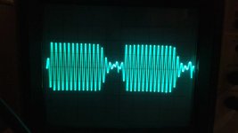
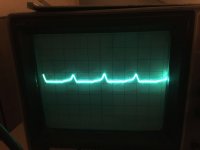
I am trying to crack down a fault with a function generator that I recently acquired: HP 203A. The output waveform has a repeated distortion (see attached picture) and this happens on every output channels and multiplier selection and frequency. I checked the supply voltages (+15 and -15) and they each have periodic ~.1V jumps every 2.5ms (see the -15V supply in attached picture).
I suspected that the Power Supply portion of the function generator is to blame so I went on and focused on it. When I lifted C2 can capacitor from the circuit and measure it's capacitance, it's value showed up as 0.1nF and slowly climbing when I should be reading 1000uF. The C1 capacitor reads 1100uF which is acceptable.
Looking at the parts list from the service manual:
C1, C2 0180-0056 C: fxd, elect, 1000uF, 50 vdcw
I think to fix my problem I should be replacing C2, although I am not sure about can capacitor breakdown symptoms. My knowledge about these type of circuitry is really limited and I am mostly basing myself off of basic knowledge. Is there someting obvious I am missing out? Is there some way I could test further to make sure that C2 is the real issue? Also, what is the typical servicing method for these HP instruments? (ie: Should I just go and buy an regular electrolytic 1000uF 50V and not care about looks? Should I restuff the can? Should I find a NOS replacement?)
Just trying to get insight on this project, any help is appreciated!
Thank you 🙂
Charles
.jpg")
First post on this forum!
I am trying to crack down a fault with a function generator that I recently acquired: HP 203A. The output waveform has a repeated distortion (see attached picture) and this happens on every output channels and multiplier selection and frequency. I checked the supply voltages (+15 and -15) and they each have periodic ~.1V jumps every 2.5ms (see the -15V supply in attached picture).
I suspected that the Power Supply portion of the function generator is to blame so I went on and focused on it. When I lifted C2 can capacitor from the circuit and measure it's capacitance, it's value showed up as 0.1nF and slowly climbing when I should be reading 1000uF. The C1 capacitor reads 1100uF which is acceptable.
Looking at the parts list from the service manual:
C1, C2 0180-0056 C: fxd, elect, 1000uF, 50 vdcw
I think to fix my problem I should be replacing C2, although I am not sure about can capacitor breakdown symptoms. My knowledge about these type of circuitry is really limited and I am mostly basing myself off of basic knowledge. Is there someting obvious I am missing out? Is there some way I could test further to make sure that C2 is the real issue? Also, what is the typical servicing method for these HP instruments? (ie: Should I just go and buy an regular electrolytic 1000uF 50V and not care about looks? Should I restuff the can? Should I find a NOS replacement?)
Just trying to get insight on this project, any help is appreciated!
Thank you 🙂
Charles
Attachments
Last edited:
Hi - If C1 measures bad and C2 measures Ok, help me understand the reasoning you are using to replace C2. Maybe I'm missing something.
Also - If you post a picture of those C1/C2 capacitors, we may be more helpful on guiding regarding specifications.
Also - If you post a picture of those C1/C2 capacitors, we may be more helpful on guiding regarding specifications.
When I lifted C1 can capacitor from the circuit and measure it's capacitance, it's value showed up as 0.1nF and slowly climbing when I should be reading 1000uF. The C2 capacitor reads 1100uF which is acceptable.
Hi jordheis, I just realised that I have mixed up C1 and C2 in my text. Sorry about this, it has been edited.
Was there any remaining DC charge on it when you started measuring?...it's value showed up as 0.1nF and slowly climbing when I should be reading 1000uF.
Is that regardless of all control settings on the front panel, no matter what the erroneous waveform timing is at 2.5ms intervals?...they each have periodic ~.1V jumps every 2.5ms...
I made sure the capacitor were drained before measuring and yes the voltage spike is caused regardless of the frequency setting
I'd start by replacing it with a similar-value cap on hand. That said, if the ripple on the supplies really is only 0.1V peak, it's unlikely to be the cause of the issues you're seeing here (although it's worth servicing the power supply to make sure it's meeting specifications before you even think about calibrating this thing).
When it comes to servicing ancient HP equipment:
-No harm in using modern components where necessary. Certainly no reason to "restuff" an old can capacitor or seek out a NOS one.
-Try to keep the design as close to the original as possible. HP typically did an exceptionally good job of designing test equipment. The odds of you understanding the design better than the person who designed it are slim to none.
-There's really no need to go through and do a "blanket recapping". This was cream-of-the-crop test equipment back in the 1960s, and it was built using the best parts available at the time. Even to this day, I see very few capacitor failures in 1960s and 1970s HP equipment.

- Home
- Design & Build
- Equipment & Tools
- HP 203A VARIABLE PHASE FUNCTION GENERATOR Troubleshooting Germanium Transistor Fault