
Welcome to the forum!
I've attached a service manual found on the web.
Would you advise where the wires you show in your photo appear in the schematic?
What is the history of the amp? You report low volume in left channel, but does it sound clean or distorted? Please provide details.
Please be safe while troubleshooting!
Attachments
Thanks for that!
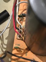
Those wires are on the power amp board center.
I swapped the transistors and made no difference. Yes everything clean no static. I purchased the amp as have always had an interest in old electronics and used to have one back in the day.
Fuses are good.
Those red and white wires attach to the control amp board and if I reverse that connection the problem moves to other side.
I am thinking there is a protector relay or something that is done.
I get maybe 2 % output.
Everything looks good nothing looks burnt or out of place.
The only thing I have seen is that on one of the transistors I get 600mV when operating and the other 3 around 150mV. When lower sound they all go to 600mV.
If I am to provide any help, I need more explicit details.
The part layout details provide some data, but I need to localize the behavior to specific part references in the schematics. I surmise you may be referring to voltage changes in Q102 and Q202 on the control board. Would you confirm if this is correct? What are you doing to cause this change--- muting switch, S5? If this is correct guesswork, would you report the base and collector voltages for Q102 and Q202 for each state of the mute switch?
Thanks.
I believe that indicates the problem is on the function switch board. Page 10 schematic does not show wire colors but there are 3 wires from function switch board to control amp board.Those red and white wires attach to the control amp board and if I reverse that connection the problem moves to other side.
I am thinking there is a protector relay or something that is done.
Lets start at the beginning: 1 not killing or injuring yourself. >25 v from one hand to the other can stop your heart. Do not use 2 hands to test the amp with the power on. Use an alligator clip lead to connect the black lead of DVM to speaker ground or analog ground (ring of RCA inputs). Such can be bought in packs of 10 from partsexpress.org . Big distrubutors are afraid you will try to test 460 vac panels with 60 v rated boots and kill yourself, so they won't sell them. The clips from fluke are suitable for 460 vac and too bulky for microelectronics.
Do not wear metal on hands wrists or neck. No rings. 1 v at high current can burn your flesh to charcoal.
Wear safety glasses, parts explode and solder splashes, especially desoldering.
2. acquire tools. DVM, clip leads, flat & phillips screwdriver big & small, needle nose & slip joint pliers, 1/4 nutdriver (part of 6 way screwdriver) diagonal cutters, wire stripper, soldering iron, tin lead solder, desoldering tool, safety or reading glasses. For amps that blow fuses, tungsten 60 w light bulb in a box with a breaker socket & plug, to limit current of amps that have shorts. Goes between the AC plug and the wall socket. For amps with volume or distortion problems, analog voltmeter with 20 vac and for input 2 vac scales ($18), else an oscilloscope and 2 scope probes ($100). Schematic for amp helpful but not totally necessary. Trash speakers that you do not mind blowing up. Else protect speakers with 2200 uf non-polar capacitors series the hot, or (used) 2200 uf up polar capacitors wired + to + and in series with each speaker. Sound source. I use a pocket radio turned down to 1/4 volume, cable from earphone jack to 2 RCA jacks. Use earphones to tune onto station. Check with earphone that sound out is balanced. Warning, some cheap radios (craig) drift off station in 30 seconds. Heat sink compound for blown up amps. Non-flammable contact cleaner for controls. If flammable, use only outdoors or 6 m away from flame, and electricity turned on or off. Use a fan with flammable contact cleaner.
3. No action, no lights, check fuse. Lights, no sound, check dc power supplies.
Swapping transistors is not useful. Amateurs make about 33% bad solder joints. Bad solder joints inject more problems. Likely suspects of old amps that died gently, dirty or oxidized controls or switches. Oxididized protection relay contacts. Oxidized connectors, including ground. Oxidized contacts between ICs and the socket. Electrolytic caps that are dried up, overvalue and high ESR. Or exploded. Zener diodes and regulator IC's in power supply.
Amps that were shorted by speaker wiring or shorted drivers in speaker, output transistors, output emitter resistors, drivers, etc. Cheap amps, the driver transistor that overheated because they did not include a heat sink.
So your amp works, but has low music. You are into the AC music realm. Insert sound source producing 1 vac in tuner jack, set source switch to tuner. Block negative probe of AC analog voltmeter with a .047 uf >150 v capacitor. 2 clip leads. or use scope. Trace through the function switch board looking for the beginning of the sound inbalance. 2 vac scale useful here, although 20 vac scale can work. Or use scope if you have one. RMS DVM can be used without the capacitor, but miss ultrasonic oscillations over 7000 hz, so I view them as a big waste of $160.
Happy hunting.
Last edited:
If I am to provide any help, I need more explicit details.
The part layout details provide some data, but I need to localize the behavior to specific part references in the schematics. I surmise you may be referring to voltage changes in Q102 and Q202 on the control board. Would you confirm if this is correct? What are you doing to cause this change--- muting switch, S5? If this is correct guesswork, would you report the base and collector voltages for Q102 and Q202 for each state of the mute switch?
Thanks.
The values for Q102 and Q202 are zero and 7.35v regardless of mute or not. Same for both.
Does it have protection relays? I was guessing that it was dirty or stuck but can find it?
So found something. First thing I must say is complete respect for this hobby or industry as it’s both rewarding and fascinating!
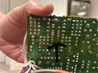
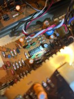
Doing some more digging around I found that the circled piece looks like it’s not soldered correctly or solder fell off. On the control amp board. See pics.
Tips on re soldering how much do I put? Same like opposite side?


Doing some more digging around I found that the circled piece looks like it’s not soldered correctly or solder fell off. On the control amp board. See pics.
Tips on re soldering how much do I put? Same like opposite side?
You better hope that is not it. That is a part you probably cannot buy.
You may clean the top side with 70% isoprophyl alcohol and a cotton ball or Q-tips. Looks like flux.
To advance the process, does the red & white 3 pin connector connect the control board to the function switch board?
You may clean the top side with 70% isoprophyl alcohol and a cotton ball or Q-tips. Looks like flux.
To advance the process, does the red & white 3 pin connector connect the control board to the function switch board?
It looks like the solder is not there and needs to be re soldered. Should I not solder it? You can see where the solder used to be in the picture from bottom side.
The red white connector goes from amp control board to power amp board.
The red white connector goes from amp control board to power amp board.
Yes, you've spotted suspicious joints at about 6:30 and two more at about 3:00. If you're very lucky, they may be culprits.
Clean solder side with denatured alcohol. Remove existing solder with solder wick if available. Add a bit of rosin flux (liquid or paste) and solder with 60/40 rosin core solder. Try to mimic the appearance of exiting joints.
Clean solder side with denatured alcohol. Remove existing solder with solder wick if available. Add a bit of rosin flux (liquid or paste) and solder with 60/40 rosin core solder. Try to mimic the appearance of exiting joints.
Diagnostic checks: measure opamp out voltage at IC201 pins 2 and 13. I believe they should be near 0V, but you can confirm this assumption by measuring at IC101.
With power off, measure resistance to ground of R142 at board-to-board connection, positive meter lead on the resistor. Resistance should be about 105k, (R141+R142). Repeat at R242. Note that these measure points correspond to the collectors of Q102 and Q202.
Repeat these resistance measurements with power on. Be sure speakers are not connected, as the ohmmeter will inject a large transient into the PA. At moment of power on, Q102 and Q202 should short these nodes to ground to effect muting, then release to enable signal. This should manifest as rise in rise in indicated meter resistance.
I believe I erred earlier when I asked for measurements in both S5 Mute switch positions. I don't find any direct connection to S5 and believe Q102/Q202 serve only to suppress turn-on transients.
An open cap at C139/C239 might explain behavior you observed when you swapped red and white wires. (I'm uncertain which wire is which channel.)
Last edited:
- Home
- Amplifiers
- Solid State
- Hi Everyone First post — Want to learn more about old amps and repairs