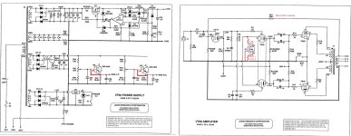
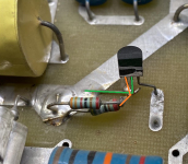
I've got an interesting one that I've never seen before, I'm hoping someone would shed some light on why this was done. This is an audio research vt60. It's had some mods done, and the schematic that's floating around is about half incorrect, but it seems like someone modded it to use this mosfet on the cathodes of the driver tubes, with what I think is the gate tied to ground, as I understand, this just makes it a fancy diode?
Someone painted over the markings on the fets so I've been having trouble figuring out the part number of it, I need to pull it and check it, but I just wanted to ask, has anyone seen anything like this?
Excuse the crudity of the schematic, I'm trying to red marker all the changes on it.
Someone painted over the markings on the fets so I've been having trouble figuring out the part number of it, I need to pull it and check it, but I just wanted to ask, has anyone seen anything like this?
Excuse the crudity of the schematic, I'm trying to red marker all the changes on it.
Attachments
It's a simple constant-current sink. It will either be a depletion MOSFET, or an LM317L, hard to make out the pin arrangement from the photo.
Last edited:
Interesting to see that audio research have abandoned both their symmetric chain and simple phase inverter and also started with ultra-linear power stage.
The above amp vt-60 has a LTP with a 10k resistor and the above hack seems to be a ccs implementation.
Would be nice to have some measurments ans see if this improves the vt-60
The above amp vt-60 has a LTP with a 10k resistor and the above hack seems to be a ccs implementation.
Would be nice to have some measurments ans see if this improves the vt-60
I was able to scrape off just enough of the paint and it seems to be marked 2535, maybe a DN2535?
hard to make out the pin arrangement from the photo.
Attachments
One follow up question if I can get away with it, the resistors that go from source (if these are indeed DN2535) to ground aren't the same on both sides, one side reads 174 ohms, the other 200 ohms, and both are made up of 2 in parallel, these aren't critical right, I can probably just use a single 200r on both sides, or is there some kinda of ultra precise tuning going on?
I want to rebuilt this a bit nicer and less bodgy.
I want to rebuilt this a bit nicer and less bodgy.

I suspected as much, I wonder if a trimmer wouldn't be more elegant.
I'll have to measure it once it's running, the damn 7808 regulator was dead so I'm waiting for that to get here.
Thanks for the hints!
I'll have to measure it once it's running, the damn 7808 regulator was dead so I'm waiting for that to get here.
Thanks for the hints!
Okay, I'm fully down the rabbit hole now learning how to use CCS. I think I'm starting to get it.
I've noticed in some of the examples I've found, that a 100r gatestopper is used sometimes, some folks say it's mandatory, others don't seem to care. Would it be a good idea to add some in this case? I'm going to clean this whole mess up, and I'd like to do it properly.
I've noticed in some of the examples I've found, that a 100r gatestopper is used sometimes, some folks say it's mandatory, others don't seem to care. Would it be a good idea to add some in this case? I'm going to clean this whole mess up, and I'd like to do it properly.
Grid stoppers are sometimes needed to keep a tube (or any active délement) from oscillating. This i smost needed
for high-Gm tubes like ECC88. But i cannot find a reason to remove a gridstopper.
As for the vt-60, i guess the best you can do is to return it to factory configuration removing all "mods"
for high-Gm tubes like ECC88. But i cannot find a reason to remove a gridstopper.
As for the vt-60, i guess the best you can do is to return it to factory configuration removing all "mods"
I've thought about that too, on the factory schematic, it's just a 10k resistor connecting both cathodes to ground. The trouble is, a few of the modifications (stuff that's not on the schematic) appear to be factory revisions. This ccs certainly isn't a factory mod, and pulling it out and putting the 10k resistors back in might be the best course of action, though now that I've been reading and trying to understand ccs as it relates to tubes leads me to wonder if the performance is significantly better with it.As for the vt-60, i guess the best you can do is to return it to factory configuration removing all "mods"
If it is, I'd like to just rebuild the mod and keep it, but if we're talking about a little more distortion or something minor, I might just delete it.
Yeah, I've e-mailed them, but I think they're working slowly through the new year. In the last e-mail I sent, I told them I'd learned it was a ccs mod, gave them the number of the fet, and shown them the edited schematic, so I'm waiting to hear back after they show the question to their tech.I think you can mail AR and ask if and if so any modifications are to be done on vt-60.
The last time they replied, he told me there have been "several revisions" to it, some of which have been done in what looks like a factory manner, like the removal of the transistors in the negative bias supply. This board has a neatly soldered factory looking jumper across where they are on the only vt-60 schematic I can find floating around.
Edit: What it almost looks like is what they did on the vt-100.
One last question (I should stop saying that because I know it probably won't be lol) I'm reading in various postings that when using ccs in the ltp, the plate resistors should match. They do not in this design.
Should they?
Should they?
Regarding plate resistors ; with a "classical LTP" the amplification is limited thus the second triode won't be replicating the first, thus a larger plate resistor on the second triode will partially compensate. When ccs
is used the triodes will be better (but not perfect amplifying devices) and the plate resistors may be equal. The
rest of the difference is up to the NFB to compensate for.
In your case the CCS seems to be a half-done job. I'd measure dist before and after reverting to stock configuration.
is used the triodes will be better (but not perfect amplifying devices) and the plate resistors may be equal. The
rest of the difference is up to the NFB to compensate for.
In your case the CCS seems to be a half-done job. I'd measure dist before and after reverting to stock configuration.
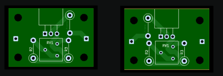
The more I read about ccs used like this, the more I think I want to keep it. Right now I'm leaning towards just rebuilding it exactly as it is, but change the resistors around a little bit so I can stick a trimmer in there for a little bit of adjustment. Maybe try a cascoded arrangement at some point.In your case the CCS seems to be a half-done job. I'd measure dist before and after reverting to stock configuration.
I've ordered a few more 2535s in both package types and a slew of resistors (in my typical mega-overkill size lol) to play with and see what I can come up with.
I need to design a little board to do this with, dead bugging on the top of the circuit board rubs my fur the wrong way a bit.
The higher the tail impedance, the more closely the plate resistors need to be matched. A CCS has very high impedance, so you should use matched plate resistors.I'm reading in various postings that when using ccs in the ltp, the plate resistors should match. Should they?
Awesome, thanks for all the help so far, I appreciate it while I'm trying to learn this stuff!The higher the tail impedance, the more closely the plate resistors need to be matched. A CCS has very high impedance, so you should use matched plate resistors.
One more question, do you think there's any benefit to adding a gate resistor? AR doesn't use one, and this didn't have one, but if it's helpful, I might add a 100r gate resistor since I'm going to try and have some small boards made for this to sit on.
A gate resistor is probably not necessary, the connections are very short, the source has a nice resistor in there, the drain is working into a low impedance, so I would think oscillation due to lead inductance would be very unlikely. But as the old saying goes "If you want an oscillator, build an amplifier. If you want an amplifier, build an oscillator"!
- Home
- Amplifiers
- Tubes / Valves
- MosFET in driver tube cathode?