Hi,
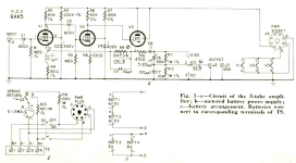
I have ATTEN ADS 1062CML 60MHz 2-channel digital oscilloscope and it has a major problem - poor input sensitivity. Some applies to other consumer grade digital oscilloscopes with cost price around several hundreds USD or Euro. By a chance I found in very old Radio-Electronics magazine low-noise (300 uV output noise with input shorted) high-sensitivity amplifier based on 6AK5. Frequency response 5Hz - 1 MHz, amplification factor 100, max input voltage 0.25V. Amp is immune to high-voltage overload typical for vacuum tune circuits. I powered it from 4 x Li-ion 18650 batteries with nixieclock.org NCH6100HV (12-24V input, 85-235V/24mA output) buck step-up converter and LM317 for 6.3V filament. Both available on Aliexpress.
Article in PDF format and LTSpice files (original schematic and my mods) enclosed in ZIP archive.
I assembled original schematic on prototyping board and it didn't worked as expected, it oscillates no matter what. Additional symptom was low plate voltage on first two 6AK5 (around 45 - 50V with B+ = 135V). Verified assembly many times, replaced NOS Siemens 6AK5 with 6Z1P, no changes. I suspected noise from NCH6100HV buck step-up converter but its not the case since amp is connected with C-R-L-C filter with electrolityc, film and ceramic capacitors.
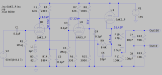
Finally I have given up and brought this amp to my friend who have more experience. He modified screen grid bias (added R14 and R15 on LTSpice schematic) so voltage (on screen grid) is about 30-31V. Amp is working now. This all is quite strange since it was assembled in Radio-Electronics test lab and they confirmed amp data.
Anyone can comment this issue? Thanks in advance.
I have ATTEN ADS 1062CML 60MHz 2-channel digital oscilloscope and it has a major problem - poor input sensitivity. Some applies to other consumer grade digital oscilloscopes with cost price around several hundreds USD or Euro. By a chance I found in very old Radio-Electronics magazine low-noise (300 uV output noise with input shorted) high-sensitivity amplifier based on 6AK5. Frequency response 5Hz - 1 MHz, amplification factor 100, max input voltage 0.25V. Amp is immune to high-voltage overload typical for vacuum tune circuits. I powered it from 4 x Li-ion 18650 batteries with nixieclock.org NCH6100HV (12-24V input, 85-235V/24mA output) buck step-up converter and LM317 for 6.3V filament. Both available on Aliexpress.
Article in PDF format and LTSpice files (original schematic and my mods) enclosed in ZIP archive.
I assembled original schematic on prototyping board and it didn't worked as expected, it oscillates no matter what. Additional symptom was low plate voltage on first two 6AK5 (around 45 - 50V with B+ = 135V). Verified assembly many times, replaced NOS Siemens 6AK5 with 6Z1P, no changes. I suspected noise from NCH6100HV buck step-up converter but its not the case since amp is connected with C-R-L-C filter with electrolityc, film and ceramic capacitors.
Finally I have given up and brought this amp to my friend who have more experience. He modified screen grid bias (added R14 and R15 on LTSpice schematic) so voltage (on screen grid) is about 30-31V. Amp is working now. This all is quite strange since it was assembled in Radio-Electronics test lab and they confirmed amp data.
Anyone can comment this issue? Thanks in advance.
Attachments

Definitely!
@linuxguru: Does the magazine show a photo of the construction details? I guess the components of each stage require an individual shielding cage, i. e. three cages in total.
Best regards!
@linuxguru: Does the magazine show a photo of the construction details? I guess the components of each stage require an individual shielding cage, i. e. three cages in total.
Best regards!
No, only metal enclosure.Does the magazine show a photo of the construction details? I guess the components of each stage require an individual shielding cage, i. e. three cages in total.
An easier way to go is buy a dedicated sensitive millivoltmeter and use
the amplified ac output as the vertical signal of the scope. These can be
cheap on the used market and have lower noise than what you built.
the amplified ac output as the vertical signal of the scope. These can be
cheap on the used market and have lower noise than what you built.
A good bench meter will fit the bill. I use an old Keithley 195. It claims 100nV resolution on DC.
Depends on what bandwidth you need. I use an OPA1641 as a non-inverting x100 amplifier, but it certainly won't go to MHz. Sadly, not many bench meters have a pre-amplifier output, but if you have one, than that's a handy cheat.
Post 6 : this thread is about ac and not dc, no hf also, op claims 1 MHz for the item he built.
Also, dmm units do not have an output for use with the scope which is the original intention.
Also, dmm units do not have an output for use with the scope which is the original intention.
Member
Joined 2009
Paid Member
Open loop gain is about 60dB, 20dB feedback applied.
If it oscillated before R14 and R15 were added, your build is conditionally stable at best.
Which means that the problem could return any time, depending on source or load impedance or tube aging.
Parasitic capacitances and wiring inductances can cause one build to appear stable, another one unstable.
As an additional precaution I would at least fit 1K grid stoppers on all 3 control grids and 100 ohm stoppers on all 3 screen grids, short and directly soldered to the tube pins.
In early neuroscience investigations, scientists DIY 6AK5 amplifiers for
single cell brain probing. 6AK5 made its contributions.
single cell brain probing. 6AK5 made its contributions.
We built a SS version decades ago, with similar specs, draws no more than half a mA from a 9V battery.
Hameg ?
An even simpler single chip version could be made around a uA733 video amplifier, xxMHz bandwidth but lower input impedance.
https://www.ti.com/lit/gpn/ua733
Hameg ?
An even simpler single chip version could be made around a uA733 video amplifier, xxMHz bandwidth but lower input impedance.
https://www.ti.com/lit/gpn/ua733
Attachments

Member
Joined 2009
Paid Member
Just an olden Goldie - check all the solder joints, a dry joint can have unintended consequences.
I don't view 500uV/division (5mV/division for 10:1 probe) as poor sensitivity (Siglent SDS series)
Noise increases with the square-root of bandwidth and with the square-root of resistance. 'Scope 10:1 probes have 9M resistors in series with the input which introduces lots of thermal noise.
A 200MHz 'scope without bandwidth limiting probing a 10k circuit will have about 200µV rms thermal noise best case (no allowing for bypass capacitance in the probe system), so 500µV/div seems perfectly adequate for wide-band use. With input shorted I see about 50uV of fuzz on the trace. At 10:1 with shorted input I see about 700µV of fuzz which is fundamental to the probe. No point having more gain that would just amplify the fuzz.
If you want to look at smaller signals you need band- or low-pass filtering in the scope to eliminate the broadband noise otherwise there is little point increasing sensitivity. An external amplifier with gain and filtering is usually required to look at low level low bandwidth signals unless the 'scope has flexible internal filtering.
Input sensitivity of the scope in post 1 is 2mV/cm, not "500uV/division".
However both numbers are not sufficient to analyze noise and hum in a
nice way and preamplification as with a millivoltmeter is useful, see post 5.
The preamp introduced in post 1 has a bandwidth of 1MHz, not 200.
The OP started an identical thread somewhere else:
https://audiokarma.org/forums/index...r-as-add-on-for-digital-oscilloscope.1076231/
- Home
- Amplifiers
- Tubes / Valves
- 6AK5 amplifier as add-on for digital oscilloscope