I have been spending quite a bit of time trying to understand transmission lines, and have really been trying to come to grips with the prevailing thought of cross sectional area doesn't matter. I absolutely am raising this question not to troll or try to poke holes, because clearly folks are designing good systems using the suite of available tools (akabad, spicytl, etc.). Of course there is Comsol, but for most of us, this is way too expensive.
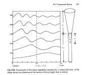
My son sent me a book on the physics of musical instruments (Fletcher and Rossling), and there is a section describing the harmonics of pipes and cones. According to them, there are cutoff dimensions for the various harmonic modes (they highlight 4 in a cylindrical world), the cutoff for these ranges from 1.84 c/a to about 3.5 c/a. (c=speed of sound, a=area). My gut analysis says that we are above these cutoff regions in most TLs for most frequencies.
Additionally, whilst I see discussion on tapering vs straight lines in terms of the length of the line, I don't see explicitly this being used to target the various impedance ranges. (Or at least how I understand it). (see attached screenshots)
It has taken me a while to understand this whole impedance matching thing, or at least telling myself that I understood things.
I am limited in my options since I am on a mac, but I have redusted off spicytl, and have been trying to have responses match what is predicted by theory (and some very complicated math), and I don't see these happening. In fact, @planet10 , who knows more on this than I ever will on this, specifically told me Sd doesn't matter. And he has real world experience.
And, I notice that a "typical" approach is to stuff the line until it "sounds" good. And, some results are truly amazing. Others (such as I would probably design) might look good on paper (aka., modeling), but maybe not so good in real life.
I am curious about the tweaking, since I do see a gap between the physics and the model, and do not know enough to know the limits. But when I look at the graphs I see how area and taper rate should very much affect impedance. In fact, tapered lines should have more impedance peaks than straight?
So to my question:
When modifying the TLs, are people also measuring the driver impedance response across the frequency range in the TL, and using this to tune, or are people using the acoustic response, which also includes the baffle?
Attachments
Long story short.
It is a reflex with a port that is too big and too long.
Maybe more fake port bass like any reflex by making it too long.
But a wealth of confusing extra data and theory to fix the resonant barfing
from a port that is too long.
No wires to a port, so same old velocity ramp delayed longer.
So you have a scrumptious amount of extra data and theory
like offset and tapers, and plenty of stuffing to lower efficiency
and fix the extra resonance problems created by being too long.
You can weasel a 85 Hz or 55 Hz driver.
Or just get a real woofer that goes to 35 to 30 Hz
6 months to 2 years of painful simulation and theory.
Its fun, till you port something at 18 Hz
Any finally hear 35 Hz not imaginary 20 Hz with actual electro/ mechanical authority
AKA ported or Sealed Subwoofer with the same old 6 to 8 dB of boost you add anyways.

the prevailing thought of cross sectional area doesn't matter
A transmisison line is specified with a cross-section, a length, taper, driver offset, any mass-loading, and the damping.
Given the wording of quoted bit, i have to ask where is the "land of cross-section does’t matter”?
And, I notice that a "typical" approach is to stuff the line until it "sounds" good. And, some results are truly amazing. Others (such as I would probably design) might look good on paper (aka., modeling), but maybe not so good in real life.
Typically a TL modeled by someone who knows what they are doing ends up being one of the former, someone using classic techniques might get something OK 1 time out of 10 tries.
Dampimg is on eof the tools you use to Low Pass the fundemental harmonic and skill the unwanted ones. In a musical instrument the resonaces are maximized, with holes o change he tuning dynamically by oonng or closing them.
Other LP tricks are driver offset (Zd), mass-loading, line expansion (happens when you fold the pin and don’t install a deflector. Helmholt resonance chamber(s) can be used to target specific harmonics.
dave
Last edited:
a couple of years ago I fumbled around for days trying to get wine running on my m1 Mac. Including a trial version of parallels and crossover. I found some instructions on apple insider which linked to a GitHub article which seemed to work. With the availability of ChatGPT, you could also ask it to help for example (I didn't test it though) https://chatgpt.com/share/67707243-8510-8013-97f4-051a35e4d73a
A further option is to run an ARM version of windows in UTM using CrystalFetch for the latest build. Both options run HornResp fine.
A further option is to run an ARM version of windows in UTM using CrystalFetch for the latest build. Both options run HornResp fine.
Thanks @woodo, while I had glimpsed at Martin King's models briefly early in, I had slipped past too quickly to the models, without understanding the derivation. I am absolutely going to have to remember modeling in wave space and weekend dinner more time there.
But fundamentally, I think it answered my question. At least I think so. In simplifying to the one dimensional space, the ability to capture the impact of the various other modes of resonance in the model disappear.
For example, I would expect that the ratio of x/y (x*y being cross sectional area) to have a noticeable impact on line impedance where dimensional length exceeds the harmonic cutoff for the various modes.
As I understand the model, only the harmonic in the length direction are considered, which would be the bass that in the focus of port SPL?
But surely there is impact on the driver response at the higher frequencies too? And not just in the harmonic multiples defined only by the length. For example the quarter wavelength of 1500 Hz is about 5 or 6 cm?
Such says the man who has yet to build one!
But this has absolutely got my curiosity piqued, and I so much appreciate you folks taking the time to help me understand this. In graduate school my focus was on the breaking point of mathematical models in natural systems, so this probably explains why I am scratching at this so much. I hope comments are coming off as critical of anyone or any approach. This is just a case of a curious idiot trying to understand why his view of the world once again doesn't match reality.
So go brute-force a piece of cardboard into any BR to form a line, and listen to music or test tone. The quarterwave resonance can be heard at the port exit (why not?) and IME largely agrees wth MJK math prediction (which can be done in-head). Higher frequencies get absorbed by the folds (and minimal stuffing) so in my applications (many folds to save space and even out resonances) is mainly of theoretical interest. (Like you) I didn't see a simple formula for quarterwave SPL as a function of CSA (dependence) -- which the NLA MathCAD sheets (and descendent modellers) surely implement.But surely there is impact on the driver response at the higher frequencies too? And not just in the harmonic multiples defined only by the length. For example the quarter wavelength of 1500 Hz is about 5 or 6 cm?
Such says the man who has yet to build one!
I had asked some of the same questions....
(Addendum)
Supravox still wins the "smile-on-face" contest. Bass (A-) is clear and deep just lighter than some. In comparison, the original labyrinth bass would be B- and the simplified TLonken shown below B+. The gap between 1.5m and 1.25m line-length is partially mitigated by the "Area Ratio" effect (MJK Table 1, courtesy @planet10 ) and more/easier stuffing: 1.5m 1:6.25 taper effective 1.47X 2.2m quarterwave frequency~40hz; 1.25m 1:7.25 taper effective 1.52X 1.9m quarterwave frequency~45hz. Eyeballing said table with a calculator, TL (reducing) taper 1:R has effective-length...
Supravox still wins the "smile-on-face" contest. Bass (A-) is clear and deep just lighter than some. In comparison, the original labyrinth bass would be B- and the simplified TLonken shown below B+. The gap between 1.5m and 1.25m line-length is partially mitigated by the "Area Ratio" effect (MJK Table 1, courtesy @planet10 ) and more/easier stuffing: 1.5m 1:6.25 taper effective 1.47X 2.2m quarterwave frequency~40hz; 1.25m 1:7.25 taper effective 1.52X 1.9m quarterwave frequency~45hz. Eyeballing said table with a calculator, TL (reducing) taper 1:R has effective-length...
All right. Wading in here:
That might have been the case 25 years ago, and it still gets repeated, usually by those who don't know the physics. Short version: it does matter. Profoundly, both from the POV of geometry, which determines the tuning characteristics, and total volume, which determines gain.I have been spending quite a bit of time trying to understand transmission lines, and have really been trying to come to grips with the prevailing thought of cross sectional area doesn't matter.
You're right to, even though it's been dealt with many times here & elsewhere.I absolutely am raising this question not to troll or try to poke holes, because clearly folks are designing good systems using the suite of available tools (akabad, spicytl, etc.). Of course there is Comsol, but for most of us, this is way too expensive.
Depends. A QW pipe (as in one sealed at one end & open at the other) has a fundamental that's a function of length & taper, & odd order harmonic modes. In the majority of cases, the harmonics are unwanted but relatively easily addressed with pipe geometry, driver & vent (if relevant) offsets. This, of course, gives the lie to the notion that they are a 'reflex' (which is what Thuras built, and not subsequent vented boxes) with over-long vents, since a/ most TLs do not have any chamber at all, and b/ a reflex box operates on Helmholtz principles, & assumes a uniform internal air-particle density & no eigenmodes (standing waves). A quarter-wave / TL enclosure that is being used to support low frequencies deliberately generates and uses standing waves for that purpose: with the afformentioned exceptions, cavity resonance doesn't apply. QED.My son sent me a book on the physics of musical instruments (Fletcher and Rossling), and there is a section describing the harmonics of pipes and cones. According to them, there are cutoff dimensions for the various harmonic modes (they highlight 4 in a cylindrical world), the cutoff for these ranges from 1.84 c/a to about 3.5 c/a. (c=speed of sound, a=area). My gut analysis says that we are above these cutoff regions in most TLs for most frequencies.
It is / is accounted for if the TL in question is an aperiodic type being used for the purpose of flattening the system impedance, i.e. a max-flat impedance TL. Since a majority are not being used for that purpose however, there isn't necessarily any specific impedance response targeted in those designs.Additionally, whilst I see discussion on tapering vs straight lines in terms of the length of the line, I don't see explicitly this being used to target the various impedance ranges. (Or at least how I understand it). (see attached screenshots)
Apart from those targeting a flat impedance, there isn't really a 'matching' objective in most cases -and then what 'flat impedance' typically means is 'as close to flat as can be achieved mechanically'.It has taken me a while to understand this whole impedance matching thing, or at least telling myself that I understood things.
It doesn't directly, other than in terms of compression or mass-loading effects, which are mostly separate from line cross section. Like other types of vented enclosure, the dominant driver characteristics are Fs, electromechanical damping (in T/S parlance the effective Qts' when amplifier output impedance and / or any series R in circuit is factored in) and Vas.I am limited in my options since I am on a mac, but I have redusted off spicytl, and have been trying to have responses match what is predicted by theory (and some very complicated math), and I don't see these happening. In fact, @planet10 , who knows more on this than I ever will on this, specifically told me Sd doesn't matter. And he has real world experience.
Not generally with relatively experienced designers; this is included as part of the initial design process & usually only requires fairly moderate adjustment / fine tuning, which is often as much about accounting for the in-room behaviour as the speaker independently.And, I notice that a "typical" approach is to stuff the line until it "sounds" good.
That's certainly true -in the same way that it applies to any speaker, whatever the enclosure load happens to be. That said -for many (not all, but many) purposes the available modelling software and / or data available is accurate enough that a reasonably experienced designer can minimise issues & it's relatively rare for them to produce an outright clunker. 😉 Like a lot of things, the more relevant, accurate data you use to start off with, the likelier you are to hit your target goal. Or to put it another way: the more you put in, the more you're likely to get out in results.And, some results are truly amazing. Others (such as I would probably design) might look good on paper (aka., modeling), but maybe not so good in real life.
Not really. In some cases, they may even suppress harmonic modes more effectively than an untapered pipe.I am curious about the tweaking, since I do see a gap between the physics and the model, and do not know enough to know the limits. But when I look at the graphs I see how area and taper rate should very much affect impedance. In fact, tapered lines should have more impedance peaks than straight?
I suspect most people measure both the frequency and the impedance response, but in this context, they're both going to show the same thing in different ways, i.e. any unwanted resonances present, and their severity. You can use either to track them down & address as preferred, just as you would with any other box load.So to my question:
When modifying the TLs, are people also measuring the driver impedance response across the frequency range in the TL, and using this to tune, or are people using the acoustic response, which also includes the baffle?
But surely there is impact on the driver response at the higher frequencies too?
Damping.
To get smooth bass in a quarterwave/TL all of the non-fundamental resonances are low passed out. Like a reflex damping is inteneded to deal with the higher frequency (potential) resonances. Also, given the same volume, the small dimensions (WxD) will be relatively smaller and easier to damp.
dave
Correct.As I understand the model, only the harmonic in the length direction are considered, which would be the bass that in the focus of port SPL?
But surely there is impact on the driver response at the higher frequencies too? And not just in the harmonic multiples defined only by the length. For example the quarter wavelength of 1500 Hz is about 5 or 6 cm?
Need to keep in mind that the cab only loads to the driver's effective upper mass corner (Fhm) where T/S theory peters out, so the rest are damped to 'taste' with stuffing/whatever:
Qts': 2*Fs/Fhm
Fhm = 2*Fs/Qts'
Fs: Fhm*Qts'/2
(Qts'): (Qts) + any added series resistance (Rs)


- Home
- Loudspeakers
- Full Range
- transmission line - theory vs. practice