The search for previous topics about this yielded nil results...
Specifications of tubes were published in books, along with examples how to deploy them.
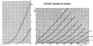
Attached is an example of the ECC83 / 12AX7 transconductance and output characteristics (scaled & merged) and shows a maximum Ia of almost 6mA (@250V).
But how accurate are these specifications? What amount of variation ('spread') of values can be expected?
In %'s, both small signal and larger types (eg PL519).
Specifications of tubes were published in books, along with examples how to deploy them.
Attached is an example of the ECC83 / 12AX7 transconductance and output characteristics (scaled & merged) and shows a maximum Ia of almost 6mA (@250V).
But how accurate are these specifications? What amount of variation ('spread') of values can be expected?
In %'s, both small signal and larger types (eg PL519).
Attachments
Well, we just had a discussion about this in another thread. There was argument about whether different brands and plate structures can change the sound of an amp, but no one disagrees with the idea that a well-made tube in new condition should pretty much conform to the specs. I've used and tested a lot of different tubes in my Williamson amplifiers, and at idle they all behave pretty much the same. Under dynamic conditions, that can change if the tube is poorly made or worn from use (or abuse). But a well-constructed and properly tested tube should behave pretty much according to the specs. Older tube amp construction techniques allowed for up to 20% variation in component values, but these days most manufacturers (and DIYers, for that matter) shoot for tighter tolerances.
Cherry and Hooper (1968, here: https://www.worldradiohistory.com/B...-Pass-Amplifier-Design-Cherry-Hooper-1968.pdf) comment on the spread of the small signal characteristics of valves at pages 89 to 91. At pages 205 and 206, they report variations in gain of a sample of 12AX7s employed in a two-stage amplifying circuit.

In general, vacuum valves can be made to very tight tolerances in geometry (which determines transfer characteristics on curves) compared to semi-cons, which are often sorted into 2:1 or even 3:1 groups for beta or Idss. By comparison, vacuum valves' working parts are so big that they can be kept to 20% or better of necessary initial values of sortable factors like mu or Gm.
Other, subtler things like materials purity, vacuum, seals, etc. are never specified directly and can't be compared between historical (generally always better, but..) and modern second-world manufacture. So, for example, maximum grid leak resistor value, G2 safe dissipation or 1/f noise cannot be assumed (or expected) to be the same in modern production, but mu values could be expected to overlap old manual values, and we must test and report to others from there, case by case, moving targets.
All good fortune,
Chris

Cherry and Hooper (1968, here: https://www.worldradiohistory.com/BOOKSHELF-ARH/Technology/Technology-Handbooks/Amplifying-Devices-and Low-Pass-Amplifier-Design-Cherry-Hooper-1968.pdf) comment on the spread of the small signal characteristics of valves at pages 89 to 91. At pages 205 and 206, they report variations in gain of a sample of 12AX7s employed in a two-stage amplifying circuit.
View attachment 1397871
That's very interesting, thanks!
For spread in tube parameters + /- 20% is mentioned and is inline with my observations of new production tubes. Old tubes we don't really know as the surviving ones have been submitted to several levels of selection, here
the only reliable source is in printed sources. However some comments from designers of contemporary tube amps
indicate that it was important to create designs that was independent of tubes parameter spreads.
the only reliable source is in printed sources. However some comments from designers of contemporary tube amps
indicate that it was important to create designs that was independent of tubes parameter spreads.
It depends on the valve. Mullard had a production process that was bang on & probably tested every valve but there was bound to be valves that failed A1 testing, these were, AFAIK sold on to re-badging outfits like Zaerix. The same was true with early transistors, you could buy a bag of ? transistors for 50p say, their specs were all over the shop.
Valve datasheets were also a selling tool, it's an ideal valve & it depends on who was buying the valves, HMS/USA government probably got some of the best as did big TV & Radio manufacturers. Add to that all the re-labeling, different storage procedures... some valves come in a simple cardboard box, mil stuff comes in the best packaging: if you've ever had your hands on one it blows your mind, bog knows how much it cost.
Tektronix aged & selected valves to exacting specs as did Marshall amps to a lesser extent, so it depends also on what you want your valve to do. What bias? At what Va etc. In my experience small signal NOS valves test at about 3 bang on out 10 ish. OP valves your lucky if you get 4 out of 20 matched, a lot are gassy. Construction of the valve also has a bearing on the matter too.
No, not Zaerix; Zaerix were exclusively Soviet. What did happen to sub-standard Mullard valves was that they would turn up in white boxes, not the full blue etc. I was always very wary of white box valves.
Tek selected the valves they'd bought so as to maximise their usage. If you look, you'll find one valve type might have various Tek type numbers, all due to their selection. Valves have pretty large production tolerances until you look at FET VTO or BJT hFE, at which point, valves start looking pretty good. But there's still a lot of variation.
Tek selected the valves they'd bought so as to maximise their usage. If you look, you'll find one valve type might have various Tek type numbers, all due to their selection. Valves have pretty large production tolerances until you look at FET VTO or BJT hFE, at which point, valves start looking pretty good. But there's still a lot of variation.
These are usefull figures.But a well-constructed and properly tested tube should behave pretty much according to the specs. Older tube amp construction techniques allowed for up to 20% variation in component values
Again this 20%!they report variations in gain of a sample of 12AX7s employed in a two-stage amplifying circuit.
Many thanks Chris, very valuable!In general, vacuum valves can be made to very tight tolerances in geometry (which determines transfer characteristics on curves) compared to semi-cons, which are often sorted into 2:1 or even 3:1 groups for beta or Idss. By comparison, vacuum valves' working parts are so big that they can be kept to 20% or better of necessary initial values of sortable factors like mu or Gm.
Other, subtler things like materials purity, vacuum, seals, etc. are never specified directly and can't be compared between historical (generally always better, but..) and modern second-world manufacture. So, for example, maximum grid leak resistor value, G2 safe dissipation or 1/f noise cannot be assumed (or expected) to be the same in modern production, but mu values could be expected to overlap old manual values, and we must test and report to others from there, case by case, moving targets.
And thanks too, Peter, for your observations which spans more time as not mentioned.For spread in tube parameters + /- 20% is mentioned and is inline with my observations...
I want to know this actually.It depends on the valve.
I'm in those business...mil stuff comes in the best packaging
Very true. But apart from the bang-&-ish: what % in general?What bias? At what Va etc. In my experience small signal NOS valves test at about 3 bang on out 10 ish. OP valves your lucky if you get 4 out of 20 matched, a lot are gassy. Construction of the valve also has a bearing on the matter too.
Many thanks for the contributions, well appreciated!!!
Also thanks EC8010!Valves have pretty large production tolerances until you look at FET VTO or BJT hFE, at which point, valves start looking pretty good. But there's still a lot of variation.
What numbers, why are tubes more strict to their specs, and why, in what degree?
Valves have mechanical tolerances on things like grid to cathode spacing (which is very small) but I suspect the main differences come down to cathode activation and that's chemistry/cooking. But FET VTO and BJT hFE are not merely cooking, but how large a sniff of the gas got into the silicon when it was heated, so they're proper variable. So whilst valves are often +/-20% on specified parameters, FET VTO can be +100%, -50% and BJT hFE might be +20%, -50% if you're unlucky. In all cases, we must design to accommodate those variations and be as insensitive as possible to them; that generally means feedback. Just be glad you're not designing/building with germanium transistors! (Very variable, very fragile, very leaky.) And as for unspecified parameters (like grid current), they could be anywhere. The real issue is not whether numbers are variable, but whether your design is sensitive to a particular parameter. At which point, it is always cheaper to redesign so that you can use "any old rubbish" (because that's generally what you will get), rather than hoping that paying extra money will get you something perfect. And valves degrade with age (it's that chemistry again) whereas the silicon upstarts are mostly stable over their entire life.
Vacuum tube valley #1 has some data and information on 12AX7/ECC83 see page 13 and onwards.
https://www.worldradiohistory.com/A...m-Tube-Valley/Vacuum-Tube-Valley-Issue-01.pdf
https://www.worldradiohistory.com/A...m-Tube-Valley/Vacuum-Tube-Valley-Issue-01.pdf
I suspect that claims that some tube makers has very tight tolerances are probably due to
selecting at the factory. Tube production is inherently relying on manual work but even nuvistors
have a comparable spread in paramaters by the app. 100 6DW4 i have coma close to. Nuvistors
were automatically mounted thus it was possible to reduce tolerances.
selecting at the factory. Tube production is inherently relying on manual work but even nuvistors
have a comparable spread in paramaters by the app. 100 6DW4 i have coma close to. Nuvistors
were automatically mounted thus it was possible to reduce tolerances.
You can take a look at some of my data measured from actually tubes here:
http://mbrennwa.github.io/curvetracedata
http://mbrennwa.github.io/curvetracedata
Thanks for clarifying. I used Zaerix as an example as can't think of any other famous re-labelers off hand.No, not Zaerix; Zaerix were exclusively Soviet.
It depends on the valve because like any other man made thing it depends on quality control & even what day of the week it was made i suppose. EG some cars made in the 70's were known as Friday cars because they were thrown together in a hurry so the lads could knock off work, get their wages & go to the pub. I've no proof that was the case with valves but Soviet era factories did sloppy work to the fill the quota. I've bought quite a few Soviet 6SN7 clones over the years, some have wonky bases & while they tested ok, there was a bigger spread of test results as compared to a batch of Mullard pentodes for instance.
When I test valves I usually stick em in three groups - VG, G & OK. VG = very good, on spec or above, closely matched triodes within a few %. G = good, within a few mA of emission say, dual triodes within 5%. OK = within 70% ish, dual triodes 10 to 20%. With regards to matching power OP valves I used to match with 5% that's quiescent current @ whatever operating conditions. I've bought matched quads from reputable sellers that were had 20% difference. However, I don't think it matters much, I tested it, there was little change in THD. See -
Lastly it depends on the application you intend to use the valve for. In a valve regulated power supply say you want your series pass valve/s to be as good as poss, but then I've used 6080's that were tired and old & well out re balance of triodes but were sufficient for the job. you can also design your circuit to deal with any inbalance. If your building a mic preamp with high gain obviously you want low noise, non microphonic good condition valve but can use a valve with 70% emission for a while in a less demanding circuit.
Edit, ran out of edit time, please delete post # 15 mods.
My 6E5P were all NIB from two different batches, and my 6C33C were all new from the same batch. Here's some statistics on the voltage gain and transconductance measured from these tubes (N is the number of samples and stdev/min/max are relative to mean value):You can take a look at some of my data measured from actually tubes here:
http://mbrennwa.github.io/curvetracedata
Some manufacturers of Special Quality tubes revealed a little bit more on spread of new tubes as well as end of life.
e.g. this one: https://frank.pocnet.net/sheets/009/e/E90CC.pdf
or this one: https://frank.pocnet.net/sheets/009/e/E83CC.pdf
or that: https://frank.pocnet.net/sheets/129/m/M8083.pdf
e.g. this one: https://frank.pocnet.net/sheets/009/e/E90CC.pdf
or this one: https://frank.pocnet.net/sheets/009/e/E83CC.pdf
or that: https://frank.pocnet.net/sheets/129/m/M8083.pdf
In general are tubes more strict to specs (by mechanical construction).
Thanks for all the contributions.
Thanks for all the contributions.
As a follow up: knowing the specs are tighter (marvalous!), where are those 'specific' dynamic specs located actually?
Take the ECC83 / 12AX7 specs: gm = 1.6mA/V, Ri=63kΩ, so μ is fixed at 100.
But on what point are these specs valid (refer to #1)? Top, median, random?
Take the ECC83 / 12AX7 specs: gm = 1.6mA/V, Ri=63kΩ, so μ is fixed at 100.
But on what point are these specs valid (refer to #1)? Top, median, random?
μ is not fixed. Datasheets include the working point where they specify μ. Also, some of them include the μ (and other like gm, ra etc) curves, depending on bias, anode voltage etc.so μ is fixed at 100.
Last edited:
- Home
- Amplifiers
- Tubes / Valves
- Tube specs variation %