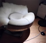
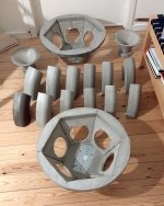
Big Flower - the logical sequel to Horn Flower.


Initial design concept study outcome - the stands in the top picture is what I will end up with.
I have had a lot of fun and learnt much from HF. Some things with them are really desirable and I wanted to see if they could be improved on... and a reason to get a 3D printer 😉
Positives: Great clarity, resolution and timing.
Negatives: Small(er) stage (but very precise), limited low bass and som midrange anomalies (comb filtering) due to that the 4 woofers plays quite high (1400 Hz)
Also the bild quality of the "box" was pretty sketchy and despite the cool "hair", it probably generated quite a lot of diffraction.
So to keep the positives and remedy the negatives, enter the Big Flower.
Same concept but with improvements (finger crossed):
Potential new negatives:
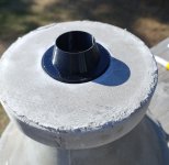
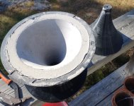
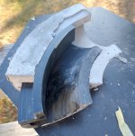
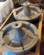
The way they where designed and realised was by 3D modelling, molds printed from PETG and casting in concrete. I like concrete - its a varm, nice and strong material 🙂
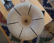
It was obvious from the beginning that I could not get a printer to make the horns in one cast so it had to be divided and later glued together. I used Sikaflex 291 for this as it had proven very stable and strong when I built my concrete baffle Line Source. All drives were glued to the concrete and still sits there safely.
I did some simulation on speaker level for the Horn FLower which gave some hints that it could work and I think the result mimic'd the simulations quite well. Therefore I didn't do any for the BF because I don't think it is needed - concept works and I feel the new dimensioning can only be better. And then there is CamillaDSP 🙂
Recipe (for a pair):
So these will be prototypes and have a number of known "errors" already. They where identified during the path of design, both in modelling, casting and dry assembly but half way in I decided to go ahead with these "less perfect" aspects as I realised that it will take one round before I get them "perfect" (never!) anyways.
So what are these problems:
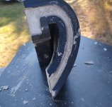
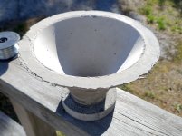
- It was harder than I could imagine to make a mold for a 60 degres part when it came to rotate a profile, make 6 of them and assemble them to a full circle unit. Sketchup could not do it. I got a plugin that was better but then I made som assumptions about how to get some room for the glue which I overestimated and got 5mm instead of 1. Next time, calculate please! 🙂 But I didn't find out until I had made 5 and then I decided to continue anyways.
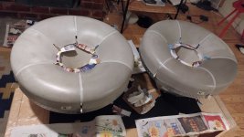
- Perhaps I have made the concrete goods a little to thick - they have been called tanker stoppers 🙂 and they will be heavy - 40kg+ - a challenge for me to handle. Better have some help during first trials.
- and several minor improvements...
To date, I have all components ready to be assembled except the stands but they are waiting order confirmation.
I will continue posting about the assembly process, measuring and dialling in.
Tnx for reading - comments welcome.
//
Initial design concept study outcome - the stands in the top picture is what I will end up with.
I have had a lot of fun and learnt much from HF. Some things with them are really desirable and I wanted to see if they could be improved on... and a reason to get a 3D printer 😉
Positives: Great clarity, resolution and timing.
Negatives: Small(er) stage (but very precise), limited low bass and som midrange anomalies (comb filtering) due to that the 4 woofers plays quite high (1400 Hz)
Also the bild quality of the "box" was pretty sketchy and despite the cool "hair", it probably generated quite a lot of diffraction.
So to keep the positives and remedy the negatives, enter the Big Flower.
Same concept but with improvements (finger crossed):
- 260mm diameter horn -> 520mm
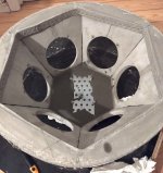
- 4pcs of 4" bass driver -> 6pcs of 5,5
- XO@1400 -> 800 (hopefully, 900/1k still ok)
- Larger volume per driver - > improved lows
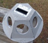
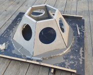
- ATH G2 inspired horn at full width should decrease diffraction
- Lower XO should mean less LF drivers c-c distance interference
- Thanks to bass driver placement and stands/mount design, the LF drivers will be much closer to wall and with less c-c despite being larger,
Potential new negatives:
- Only one cavity so now the actual horn is a pressurised surface of the closed/infinite baffle - vibration?
- Using a 1,4" CD instead of a 1" might have impact on top octave
- Increased depth (5cm) gives a longer distance between LF drivers and horn mouth... integration...
- Heavy
The way they where designed and realised was by 3D modelling, molds printed from PETG and casting in concrete. I like concrete - its a varm, nice and strong material 🙂
It was obvious from the beginning that I could not get a printer to make the horns in one cast so it had to be divided and later glued together. I used Sikaflex 291 for this as it had proven very stable and strong when I built my concrete baffle Line Source. All drives were glued to the concrete and still sits there safely.
I did some simulation on speaker level for the Horn FLower which gave some hints that it could work and I think the result mimic'd the simulations quite well. Therefore I didn't do any for the BF because I don't think it is needed - concept works and I feel the new dimensioning can only be better. And then there is CamillaDSP 🙂
Recipe (for a pair):
- Qidi Q1 Pro
- PETG 4-5 rolls (quite some trails, mistakes and re-thinking done - 3rd time a charm...)
- 2x HF SB ROSSO-65CDN-T
- 12x LF SB15nac30-4
- 3,5 x 20kg bags of fibre reinforced floor levelling concrete: Weberflow 120 Reno DR
- 2 tubes of Sikaflex 291
- Div metal parts for the hanger force distribution box
- Rubber mat for horn/basket gasket
- 2x stands out of iron and concrete (of course! 😉)
- 1 pcs of 1977837 ATH A520G2 from Cults3D - even if I wasn't planning to print this exact horn I wanted to contribute to @mabat fantastic project and products. The profile was modified and simulated in ATH/VACS to give a bit wider dispersion.
- Dedicated electronic in one box - 230V in, wifi/eth and 2 pairs / ch of cabling. TBD...
So these will be prototypes and have a number of known "errors" already. They where identified during the path of design, both in modelling, casting and dry assembly but half way in I decided to go ahead with these "less perfect" aspects as I realised that it will take one round before I get them "perfect" (never!) anyways.
So what are these problems:
- It was harder than I could imagine to make a mold for a 60 degres part when it came to rotate a profile, make 6 of them and assemble them to a full circle unit. Sketchup could not do it. I got a plugin that was better but then I made som assumptions about how to get some room for the glue which I overestimated and got 5mm instead of 1. Next time, calculate please! 🙂 But I didn't find out until I had made 5 and then I decided to continue anyways.
- Perhaps I have made the concrete goods a little to thick - they have been called tanker stoppers 🙂 and they will be heavy - 40kg+ - a challenge for me to handle. Better have some help during first trials.
- and several minor improvements...
To date, I have all components ready to be assembled except the stands but they are waiting order confirmation.
I will continue posting about the assembly process, measuring and dialling in.
Tnx for reading - comments welcome.
//
Attachments
-
 throat-exp.jpg393.7 KB · Views: 202
 -
 leaf.jpg422.6 KB · Views: 194
 -
 poor_fit.jpg380.8 KB · Views: 201
 -
 glue_prep2.jpg279.9 KB · Views: 198
 -
 must_play.jpg312.7 KB · Views: 206
 -
 basket_bottom_cast.jpg574.5 KB · Views: 202
 -
 hanger_resess.jpg483.4 KB · Views: 202
 -
 basket_rim.jpg430 KB · Views: 193
 -
 leaf_cast.jpg396.1 KB · Views: 200
 -
 throat_cast.jpg439.2 KB · Views: 193
 -
 basket_side.jpg384 KB · Views: 185
 -
 throat2.jpg297.6 KB · Views: 199
 -
 fitting.jpg239.2 KB · Views: 196
 -
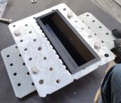 hanger_load_dist.jpg376.9 KB · Views: 178
 -
 hanger_load_dist2.jpg245.1 KB · Views: 183
 -
 knock_em_out_sidways.jpg504.3 KB · Views: 183
 -
 pottery army.jpg647.2 KB · Views: 189
 -
 chimneys.jpg652.4 KB · Views: 177
Last edited:

Wow! This one is a great concept, and IMHO, can become a really good commercial prospect since it has acceptable look for WAG.
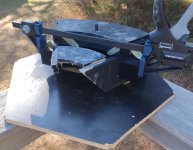
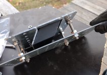
Did some test mounting today. And tried to figure out what the centre of gravity is for the speaker... this has bearing on how the stand should be designed - I want it to lean backwards towards the wall with say a 10N force - in reality this means that it will not be able to stand alone without falling backwards. It needs that wall.
Measuring from the front with all LF drivers in place, it started to tip over when the top front was 21cm from the pivot point. Without the drivers that distance was 19cm. CD driver not installed but it is even further back so I think I'm OK with this data.

The full depth is 295mm - take 210 from that and you have 95 left - so would it be correct to say that any stand that has its ancor placed to the left of the vertical line SG should make the thing fall backwards?
This is my take on this until probably someone says that I am no structural engineer - and that would be a correct statement 🙂
A few pics::

Looks a bit corny.. glad this is a view that one never will see 🙂

Here it leans on the verge of falling to the right in the picture.

Temporary bolts&nuts etc to hold things in place.
//
Measuring from the front with all LF drivers in place, it started to tip over when the top front was 21cm from the pivot point. Without the drivers that distance was 19cm. CD driver not installed but it is even further back so I think I'm OK with this data.
The full depth is 295mm - take 210 from that and you have 95 left - so would it be correct to say that any stand that has its ancor placed to the left of the vertical line SG should make the thing fall backwards?
This is my take on this until probably someone says that I am no structural engineer - and that would be a correct statement 🙂
A few pics::
Looks a bit corny.. glad this is a view that one never will see 🙂
Here it leans on the verge of falling to the right in the picture.
Temporary bolts&nuts etc to hold things in place.
//
Attachments
Last edited:
- It was harder than I could imagine to make a mold for a 60 degres part when it came to rotate a profile, make 6 of them and assemble them to a full circle unit. Sketchup could not do it. I got a plugin that was better but then I made som assumptions about how to get some room for the glue which I overestimated and got 5mm instead of 1. Next time, calculate please! 🙂 But I didn't find out until I had made 5 and then I decided to continue anyways.
I'm using 3D software that was discontinued almost a decade ago, for similar reasons.
Basically, I'm so fast with the old software, I'm not inclined to learn anything newer. It's a bummer they stopped updating. it. (I use 123D from Autodesk, you can still download it off Amazon)
85 left?The full depth is 295mm - take 210 from that and you have 95 left
I made a sketch where I would see the center if gravity:

X is the distance from the front (roughly, because the rotation center is not fixed because of roundover). Disregard the misleadingly coinciding center of gravity axis and enclosure geometry line!
The dimensioning seems slightly rotated, but I think that's correct.Would this make the distance for a stand to hit the floor at least 180mm out from the back to tilt backwards?
Also keep in mind you will need a firm and widespread base (or "tripod") to avoid the beautiful speaker falling over and getting damaged if someone accidetally bumps into it.
Thanks for helping out with this @stv - one more please.. where should I calculate the "AP" point for the stand I'm planning - at point A or B? Or perhaps between these?

As drawn above, the case of the plate for mounting the speaker and to the point A is 190mm. But I guess its point B that matter ;-) ..
//
As drawn above, the case of the plate for mounting the speaker and to the point A is 190mm. But I guess its point B that matter ;-) ..
//
If the pole and the base are connected force-fittingly (non-bending) it does not matter. In this case you might only align the center of the base with the AP-axis for even bearing of weigth on the floor.But I guess its point B that matter ;-)
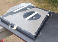
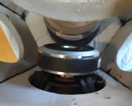
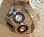
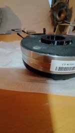
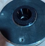
So I got all basses to fit. Now for the CD/horn assembly - I need to remove the bug screen on the CD bt I have not made such operation before so need to go careful about ot so not to mess things up..
I lower the CD in my hand between the drevers - its like a tocamac down there... I wonder what kind of magnetic envieronment really is present and if they interact in a negative way? Interference, cross-talk, less or more gap field strength...
I think I need something to protect the CD from crashing into the drivers and a thoughtful way of lowering the horn assembly into place.

//
I lower the CD in my hand between the drevers - its like a tocamac down there... I wonder what kind of magnetic envieronment really is present and if they interact in a negative way? Interference, cross-talk, less or more gap field strength...
I think I need something to protect the CD from crashing into the drivers and a thoughtful way of lowering the horn assembly into place.
//
OK on the CD mounting. Playing one instead of left plastic 260.
W.O.W
It's sick - even in this position the whole system is transformed... the release and detachment is absolutely fantastic. Its so clean and relaxed, yet so much somehow fuller - and the stage is now great - its big, its deep, unlimited... wow... the right ch hf sound broken compared... and still old bass is playing.
I am glad and my anticipation level has gone thru the roof now.. more! 🙂
Did I say wow...?

//
W.O.W
It's sick - even in this position the whole system is transformed... the release and detachment is absolutely fantastic. Its so clean and relaxed, yet so much somehow fuller - and the stage is now great - its big, its deep, unlimited... wow... the right ch hf sound broken compared... and still old bass is playing.
I am glad and my anticipation level has gone thru the roof now.. more! 🙂
Did I say wow...?
//
It's great to see someone getting the picture. Well done. Your experiments are moving in a productive direction.
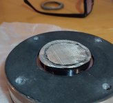
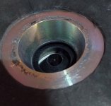
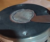
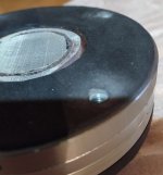
Removing the bug screen from a SB ROSSO-65CDN-T.

//
//
Attachments
-
 IMG_20241221_134819165_HDR.jpg313.6 KB · Views: 123
 -
 IMG_20241221_134656890_HDR.jpg365.2 KB · Views: 124
 -
 IMG_20241221_134614464_HDR.jpg421.6 KB · Views: 126
 -
 IMG_20241221_134130637_HDR.jpg301.5 KB · Views: 129
 -
 IMG_20241221_134028915.jpg485.5 KB · Views: 118
 -
 IMG_20241221_133857370_HDR.jpg427.2 KB · Views: 124
 -
 IMG_20241221_133738631_HDR.jpg422.3 KB · Views: 118
I am glad and my anticipation level has gone thru the roof now.. more! 🙂
Looking forward for some measurements and comparative results, whenever you can mount the heavy concrete on a stand.
Last edited:
Have been for an hour playing left ch complete but with the XO and EQ from the mother... still, it's amazing. The bass... ohh. Playing my church recordings.. what a room. OMG 😉 and piano... there is simply no give.. just granit solid sound body with an amazing amount of details. And mid-bass... so wonderfully tight and airy.... Mjau!

//
//
- Home
- Loudspeakers
- Multi-Way
- Son of HF - Big Flower