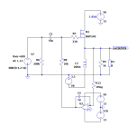
If you for some reason want to dump the output cap, this is an idea of how to deal with it and still keep it pure SE. As I have a pair of 193U and matched IRFP240s, they are used in the sketch. It will probably be a hazzle to adjust bias for both terminals to zero over the sources. A circuit breaker that monitors any DC over the speaker terminals will surely be needed.
Off course it could be adopted to the 2024 Zenductor 2.

Off course it could be adopted to the 2024 Zenductor 2.
If you do that it will be PP where 2nd harmonic is suppressed. Keeping it SE will give a spectrum with gradually falling harmonics.
thinking strictly about biasing, this way is maybe better, regarding on/off behavior
and matched IRFP240s
Attachments
Agree, if the fets where perfectly matched no trim would be needed. With matched fets they will probably follow each other with temperature, once their Iq is alike, but IRL some kind of trim will be needed to balance the pair.
Last edited:
Won't this circuit cause common mode distortion, although using R14 instead of another L would suppress it some.
A balanced circuit would not.
A balanced circuit would not.
Silly idea (I won't patent it) but if you now would make a normal single ended amp but put one end of the speaker to the center of the power supply? The amplifier using the complete voltage over both windings.
It would smoke the speaker at the slightest provocation but if you want to live dagerously, why not?
It would smoke the speaker at the slightest provocation but if you want to live dagerously, why not?
This is a Mofo.Use a transformer instead of the coils in 2 transistor push pull configuration.
Read #3.
Balanced, Circlotron or PP is out of the question.
Last edited:
Thanks Zen Mod!thinking strictly about biasing, this way is maybe better, regarding on/off behavior
Slowly got it😳. Didn´t see the obvious with the slave slowly getting biased with help of the time constant.
Question is what happens during the 2.6s?
Should be doable, eventually with separate adjustable biasing.
Last edited:
point is - use common voltage reference for both mosfets, and fiddle with time constant for second mosfet, to have them so-so same in biasing speed, thus keeping DC Offset as low is possible, in time domain
practically - one voltage source (say 9V), separate trimpots for each mosfet
in the end, you can skip any additional time constant for second mosfet
sorta same as in PP tube amps, each halve having own biasing trimpot
practically - one voltage source (say 9V), separate trimpots for each mosfet
in the end, you can skip any additional time constant for second mosfet
sorta same as in PP tube amps, each halve having own biasing trimpot
Maybe fiddle with C2 and C4 in my planned midbass amp?
C2&1kohm and C4&200ohms both give 1s.
Input driver needs lowish Zload to get desired H2.
Eventually an 1:2 input transformer could be used instead of driver stage together with a high Zin bias network, as speaker has 100dB sensitivity.

C2&1kohm and C4&200ohms both give 1s.
Input driver needs lowish Zload to get desired H2.
Eventually an 1:2 input transformer could be used instead of driver stage together with a high Zin bias network, as speaker has 100dB sensitivity.
Still thinking about how to bias the second half. What about a servo? Will not solve the start up problem, only the DC offset.

- Home
- Amplifiers
- Pass Labs
- Output capacitorless Mofo

