Hi guys,
300B Push-Pull is normally being designed in class A or class AB1, which means there is only negative grid voltage applied and there is no grid current input. While if we go w/ positive grid voltage and provide the related grid current accordly, means let 300B work in AB2 mode, how it would be?
Let‘s take a look at the integrated 300B curves, together w/ negative grid curves and positive grid curve ( up to +40V), it's the real curves and scanned by the tube curve tracer,

As you can see, the linearity of positive grid curves looks not so good, not like the curves w/ negative grid values, that's why I'm thinking to use them in AB2 Push-Pull, instead of A2 SE output stage...
Now, how would it be happened if we put the load-line on this curves and calculate the related output parameters? Pls see the picture below:

Primary Zout of OPT is selected as normal value, 5Kohms, and the Q point is selected as: -90V grid, 420V (P-K), w/ 5Kohms load, making sure the load-line does not go across the maximum static Pa, then as you can see the output power is up to about 52W, it is almost double of normal AB1 PP... in this case, positive grid value is up to +40V, and needs about 50mA grid current input...
While, the BAD thing is, Peak Ia now is coming to about 290mA when output power comes to the maximum of this design! This is almost the saturation value of this 300B, although the manufacturer does NOT provide this value, but I tested it and got this saturation point.
Normally, like WE, peak Ia of AB1 application in the 300B datasheet is recommended to no more than about 200mA, and definitely there is no reference value can be found for the application of AB2 push-pull, as this tube is originally designed to work w/ negative grid only, no one would expect to use it by positive grid value......
So, the concerns now on my side is, can this design be working, or 290mA peak Ia is safe for the tube?If I really wanna this PP amplifier to work w/ about 50W power output?🙂
Any comments are really welcome, and appreciated...🙂
Thanks
300B Push-Pull is normally being designed in class A or class AB1, which means there is only negative grid voltage applied and there is no grid current input. While if we go w/ positive grid voltage and provide the related grid current accordly, means let 300B work in AB2 mode, how it would be?
Let‘s take a look at the integrated 300B curves, together w/ negative grid curves and positive grid curve ( up to +40V), it's the real curves and scanned by the tube curve tracer,
As you can see, the linearity of positive grid curves looks not so good, not like the curves w/ negative grid values, that's why I'm thinking to use them in AB2 Push-Pull, instead of A2 SE output stage...
Now, how would it be happened if we put the load-line on this curves and calculate the related output parameters? Pls see the picture below:
Primary Zout of OPT is selected as normal value, 5Kohms, and the Q point is selected as: -90V grid, 420V (P-K), w/ 5Kohms load, making sure the load-line does not go across the maximum static Pa, then as you can see the output power is up to about 52W, it is almost double of normal AB1 PP... in this case, positive grid value is up to +40V, and needs about 50mA grid current input...
While, the BAD thing is, Peak Ia now is coming to about 290mA when output power comes to the maximum of this design! This is almost the saturation value of this 300B, although the manufacturer does NOT provide this value, but I tested it and got this saturation point.
Normally, like WE, peak Ia of AB1 application in the 300B datasheet is recommended to no more than about 200mA, and definitely there is no reference value can be found for the application of AB2 push-pull, as this tube is originally designed to work w/ negative grid only, no one would expect to use it by positive grid value......
So, the concerns now on my side is, can this design be working, or 290mA peak Ia is safe for the tube?If I really wanna this PP amplifier to work w/ about 50W power output?🙂
Any comments are really welcome, and appreciated...🙂
Thanks
Last edited:
Class AB2 is inherently full of distortion, the valves run into non linearity issues when the control grids are driven possitive. Ideal for a guitar amplifier with lots of THD.
Very few 300B are suitable for A2 without prominent distortion in A2 region.
Some chinese, russian (I use for this EH300B) robust alloy plate versions.
Driving its in A2 requiring SF or CF driver capable even quite a lot mA driving capacity to 300B grid.
BTW 300B PP in A1 capable even 20-22W output. Isn't that enough?
Some chinese, russian (I use for this EH300B) robust alloy plate versions.
Driving its in A2 requiring SF or CF driver capable even quite a lot mA driving capacity to 300B grid.
BTW 300B PP in A1 capable even 20-22W output. Isn't that enough?
Hi Jon,
Yes, I understand the THD will be increased when the tube goes into A2 mode, the thing is to balance the output power and THD now 🙂
Yes, I understand the THD will be increased when the tube goes into A2 mode, the thing is to balance the output power and THD now 🙂
Hi euro21,
Yes, I'm using China made 300B for testing now. As to the driver, I'm considering to use MOSFET as one solution to provide enough current in positive grid situation. And yes, in normal case, AB1 PP should be enough to provide around 20W output power, I just wanna try if that's possible for this tube to work in A2 for more power 🙂
Yes, I'm using China made 300B for testing now. As to the driver, I'm considering to use MOSFET as one solution to provide enough current in positive grid situation. And yes, in normal case, AB1 PP should be enough to provide around 20W output power, I just wanna try if that's possible for this tube to work in A2 for more power 🙂
Hi kmtang,
Yes, that's another way to have the driver w/ required current, but the transformer is really expensive w/ acceptable performance, so MOSFET might be the first solution for me to move on...😛
Yes, that's another way to have the driver w/ required current, but the transformer is really expensive w/ acceptable performance, so MOSFET might be the first solution for me to move on...😛
Yes, the 300B can be driven in positive Vg area, but probably don't exagerate (stay at +20V not +40V). In fact, I have a WE document refering to that somewhere -scratch my head- I'll search for it.
Note, the tube was used for power supplies too, not only audio, and then there is a different regime.
Note, the tube was used for power supplies too, not only audio, and then there is a different regime.
- I am working on a setting now along these lines too. Pentode 'repeater tube' that can pump out 250Vpp with <1%, 2.25:1+1 transformer, so very low grid resistance of 650Ω which means it can keep the tube safe, even if the grid current is 10mA. like kmtang said. [I already have another driver using 6SL7 //, 4mA CCS, and that can also give an unsane 225Vpp.].
- When I simulated the design with a 50KΩ grid resistor (fixed bias) the cathode would end up at some +100V . . . so that is no good idea with driving it in positive Vg regions.
- My 300B tube is carbon plate, like a copy of the 211. It will keep it's vaccum very very well, very low aging. Even when outside of normal use case.
- It is interesting you use the tube at so low a static voltage with a Vb of say 250V. You treat it like a 2A3 on steroids.
Yes, the +20Vp on grid is feasible.
The most limiting factor would be the OPT.
I use 300B in -very- conservative operating points (not more than 400-410V, and max. 80mA), but at +20Vp the anode current rise up even 250mA peek.
If the OPT is not designed for this, would saturate at LF, so distortion would be go to the sky.
My simulations (SF direct drive, fixed bias) shows about 34W (below 1%) output with 194Vpp grid (+20Vp over bias).
In this case the HV power about 85-90W, so over 200W PT requiring only for HV.
I don't believe that the "typical" chinese amplifier PSU designed for this.
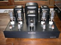
An old stuff
p-p, around 20 watt but a strong power supply and good OT
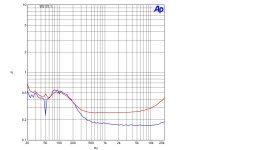
The graph is 1 watt , no FB

The THD_vs_Freq at 1 watt and 10 watt ( red line), with around 6 dB of FB
The most important thing is the quality of OT and not the positive grid
Walter
p-p, around 20 watt but a strong power supply and good OT
The graph is 1 watt , no FB
The THD_vs_Freq at 1 watt and 10 watt ( red line), with around 6 dB of FB
The most important thing is the quality of OT and not the positive grid
Walter
Attachments
Thanks triode_al, hopefully you may find this WE document somewhere for share 🙂, yes agree that +20V Vg might be more operational. The question here is I'm wondering if Peak Ia goes like 300mA, plus like 40mA Vg current, that means there is about 340mA current pushed to cathode...... the tube itself is still safe in this case? Seems you have an excellent 300B and may do more aggressive testing 🙂Yes, the 300B can be driven in positive Vg area, but probably don't exagerate (stay at +20V not +40V). In fact, I have a WE document refering to that somewhere -scratch my head- I'll search for it.
Note, the tube was used for power supplies too, not only audio, and then there is a different regime.
- I am working on a setting now along these lines too. Pentode 'repeater tube' that can pump out 250Vpp with <1%, 2.25:1+1 transformer, so very low grid resistance of 650Ω which means it can keep the tube safe, even if the grid current is 10mA. like kmtang said. [I already have another driver using 6SL7 //, 4mA CCS, and that can also give an unsane 225Vpp.].
- When I simulated the design with a 50KΩ grid resistor (fixed bias) the cathode would end up at some +100V . . . so that is no good idea with driving it in positive Vg regions.
- My 300B tube is carbon plate, like a copy of the 211. It will keep it's vaccum very very well, very low aging. Even when outside of normal use case.
- It is interesting you use the tube at so low a static voltage with a Vb of say 250V. You treat it like a 2A3 on steroids.
Not very clear on your point 4, the Q point set in the curve as showed is around 420V (P-K), -90V Vg w/ around 70mA static Ia, are you saying that?
Agree that +20V would be the most operational point if really wanna go w/ such design to build a 300B AB2 PP amplifier. I think there is no 300B manufactures will say to their customers that their 300B tube can be used in A2 mode.... I just wanna dig out more capability of this tube, if possible. Yes, OPT and PT will be the next steps to be considered.Yes, the +20Vp on grid is feasible.
The most limiting factor would be the OPT.
I use 300B in -very- conservative operating points (not more than 400-410V, and max. 80mA), but at +20Vp the anode current rise up even 250mA peek.
If the OPT is not designed for this, would saturate at LF, so distortion would be go to the sky.
My simulations (SF direct drive, fixed bias) shows about 34W (below 1%) output with 194Vpp grid (+20Vp over bias).
In this case the HV power about 85-90W, so over 200W PT requiring only for HV.
I don't believe that the "typical" chinese amplifier PSU designed for this.
Nice 300B PP Walter! Yes, might be not easy, but why not to have a try if not experienced yet 😉Why someone want to have a hard life running the 300B in positive grid?
Never!!!!!!!
Walter
Hi, you can try to drive your 300B PP with cathode follower.
Check this thread:
Check this thread:
Hi, folks,
I have a direct-coupled 6SN7 cathode follower driver idea for push-pull KT88 / 60W output. Not made any THD simulation, just basic schematic/simulation in LTSpice with voltage/current/bias numbers. This unit requires (-150V) supply apart from HV B+/6.3V. Cathode follower solves one of the fundamental problems of fixed bias push-pull stages with RC coupling.
P2 33K trim potentiometer is for controlling bias voltage, P1 10k - balance.
Any ideas or suggestions are very welcome. LTSpice files attached as zip archive.
Thanks in advance.
- LinuksGuru
- Replies: 36
- Forum: Tubes / Valves
HiNice 300B PP Walter! Yes, might be not easy, but why not to have a try if not experienced yet
in my opinion instead to play with A2 condition is much better to work on drive stage that must be linear as the 300B is, but is not simply.
I think that 6H30 soviet is the best candidate to drive the grid of 300B until 0 volt.
It is very linear but is not so simple to set as phase splitter.
Then the input can be a ECC88 that is also linear .
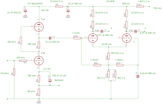
In attach the schematic of the amp I done.
The output stage is fixed bias, around 400 Vdc with 50 mA of bias
The OT is double C, ratio 27:1 with only one secondary fixed at 5 ohm
This diagram is also very good for the other amp in the photo; it works great
Walter
Attachments

According to the First Watt principle, we never ever leave 1 or even 10W - but instantaneous peaks do occur we all know, of +20dB. Vinyl. Not CD, there it is ripped off.Why someone want to have a hard life running the 300B in positive grid?
Never!!!!!!!
Walter
The 300B can handle big spikes. [Yikes - I once connected a capacitor while charged to the grid, nothing broke.] The Lowther just jumped outside its gap; but it is designed in a sloppy way to do just that.
But seriously, why not design for high peaks?
I have a large guitar style transformer, used it before for PP 300B. In almost the same driver setting you have. I used it for Quad 57's. They need the sap. <2Ω at 19kHz.
Thanks, I will take a look for detail... 🙂Hi, you can try to drive your 300B PP with cathode follower.
Check this thread:
Hi, folks,
I have a direct-coupled 6SN7 cathode follower driver idea for push-pull KT88 / 60W output. Not made any THD simulation, just basic schematic/simulation in LTSpice with voltage/current/bias numbers. This unit requires (-150V) supply apart from HV B+/6.3V. Cathode follower solves one of the fundamental problems of fixed bias push-pull stages with RC coupling.
P2 33K trim potentiometer is for controlling bias voltage, P1 10k - balance.
Any ideas or suggestions are very welcome. LTSpice files attached as zip archive.
Thanks in advance.
- LinuksGuru
- Replies: 36
- Forum: Tubes / Valves
It is not a problem due the low energy that you have at 19 kHz, this is not the main issuue.have a large guitar style transformer, used it before for PP 300B. In almost the same driver setting you have. I used it for Quad 57's. They need the sap. <2Ω at 19kHz.
My opinion is to trim the circuit at the best to reach 0 volt on 300B grid and of course some peak will exist but they aren't the problem
- Home
- Amplifiers
- Tubes / Valves
- 300B AB2 Push-Pull power output stage design and calc, Peak Ia concerns