Hello everyone,
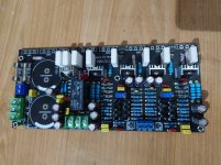
Few days ago I just bought a chaniess PCB which basic schematic is something like that (attached).
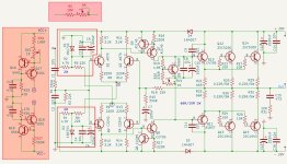
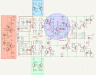
Due to my poor circuit calculation skills, I assume that the zener(15V) regulator is currently delivering 9mA.
I would like to know:
1. Should I keep the 15V zener regulator?
2. Does the 15V zener ok for RMS 28V?
3. Is it possible to add a potentiometer (shown in the red-colored box, R5 + 5K POD) to adjust DC offset?
4. Will I get any advantage if I replace the Zener with LTP (as shown in the red-colored box)?
Thank you. I would appreciate your valuable advice and opinions. 🙂
Few days ago I just bought a chaniess PCB which basic schematic is something like that (attached).
Due to my poor circuit calculation skills, I assume that the zener(15V) regulator is currently delivering 9mA.
I would like to know:
1. Should I keep the 15V zener regulator?
2. Does the 15V zener ok for RMS 28V?
3. Is it possible to add a potentiometer (shown in the red-colored box, R5 + 5K POD) to adjust DC offset?
4. Will I get any advantage if I replace the Zener with LTP (as shown in the red-colored box)?
Thank you. I would appreciate your valuable advice and opinions. 🙂
Attachments
The zener will always be faster, and therefore better...
...but is a resistor from a fixed voltage actually beneficial? It helps PSRR, of course, but the LTP might prefer a current source instead. Buts that's slower.
I would simulate both and look at stability and square wave performance.
...but is a resistor from a fixed voltage actually beneficial? It helps PSRR, of course, but the LTP might prefer a current source instead. Buts that's slower.
I would simulate both and look at stability and square wave performance.

Current source with 2 transistors is better.
I would do like with your attached image.
This would lower distortion.
I would do like with your attached image.
This would lower distortion.
"Better" as an adjective requires some kind of assignment. "Better" in terms of "sound", because audio forum, the only thing left to do is make and listen;-)
I found that a LTP phase splitter introduced some phase delay, as did adding a current source. On one simulation run I ended up needing a regular single tube phase splitter 'cathodyne', simply because both outputs were a perfect mirror in time."Better" as an adjective requires some kind of assignment.
So for areas of stability near the edge, I class a zener as better because it's simple, whereas a two transistor current source does have some delay in it, as the transistors are not perfect.
Of course not all current sources are equal, and I'd use one rather than not I guess.
Ultimately a higher voltage and a resistor might be 'best' of course, as that's sort of what a current source simulates 🙂
I found in the MOSFET Maplin amp a current source on the input LTP did indeed lower distortion quite a bit, and of course immensely helped PSRR, but I couldn't go mad and stick them everywhere.
There are supposed to be some diodes that act as current sources, but I found that the double transistor ones worked best for me.
A simple zener diode can not make a ccs.
CCS is always better than a simple resistor. For ltp, it doesn’t matter much as the inputs voltage swing is so little comparing to the power supply.
You can make CCS from 2 transistors.
CCS is always better than a simple resistor. For ltp, it doesn’t matter much as the inputs voltage swing is so little comparing to the power supply.
You can make CCS from 2 transistors.
In Engineering Speak, CMRR is high enough with a large resistor in the tail. Differential performance CAN be better with with a CCS. Would it be better here? My guess is not, unless the circuit underwent some refinements first - including hand matching the pairs and the degeneration resistors. Would it be worth a try? Sure. One improvement can drive another.
Using CCSs would be better but the capacitors C19 and C21 are connected to the wrong (ground) instead of to the rails where they belong. As shown, they will exaggerate supply noise instead of filter it.
Yeah, usually I get rid of those entirely on the CCS’s. Zeners need a .1 in parallel to quiet them, although the CMRR is probably high enough not to need it.
With active CCS the amp require much less supply voltage to be operational, +-5V are enough while with 15V zeners
15V + R2/R4 voltage drop is necessary, so a total of +-18V for this amp, wich doesnt matter much since the amp
operating points will still settle noiselessly as the VASs are switched off as long as the LTPs are not fed.
Also with an active CCS the respective LTPs currents will be generaly less matched than with zeners + R, so far for this kind
of design i generaly used 12V zeners, wich reduce the minimum supply voltage to +-15V.
In commercial designs, these decisions are usually about shaving pennies. The zener references are common to both channels using a total of 4 parts for both positive tails and 4 more for both negative tails (and no caps).
My guess is that the VAS current is either zero or limited by Q2/Q3. IE, you have the curse of a symmetric IPS. The two LTP do not agree about the precise DC offset so they ~clip in opposite directions. In worst cases, the VAS current is excessive resulting in excessive bias voltage and excessive shoot through OP current. Solutions to the symmetric IPS dilemma do exist, but generally the VAS current is undefined. Unless you are an expert, I do not recommend attempting a symmetric IPS. Marginally successful designs have avoided current mirrors etc to reduce DC gain so that differential DC Offset is not amplified.
@steveu thanks for your kind words, I have no academic qualifications on electronics, what I a have learn form experiment... I did a little experiment...
any way I have change the Resustor 220 to 100... Bias voltge increases but dancing... sometime it shows .6/.5/.4
I give up and I am going to restore the circuit as it was.... Thanks
any way I have change the Resustor 220 to 100... Bias voltge increases but dancing... sometime it shows .6/.5/.4
I give up and I am going to restore the circuit as it was.... Thanks
- Home
- Amplifiers
- Solid State
- Which is better for CCS, a Zener Regulator or a Long Tail Pair?