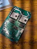
Pulling my hair out on this one. After removing two amplifier boards from their heatsink the mica insulators under the MJL21193/94 output transistors had delaminated, so I replaced them with a silicone pad. Now I have a pronounced hum and DC slowly builds up on the output until the speaker protection relay kicks out. Both boards are doing this even with the inputs shorted. Nothing is shorted through the silicone pad and the +-40v power supply checks out.
Before I dig further, I was just wondering if there is anything about the mica vs silicone that could be affecting this. Like capacitance or leakage at higher voltages?
Before I dig further, I was just wondering if there is anything about the mica vs silicone that could be affecting this. Like capacitance or leakage at higher voltages?
Hi delverboy,
You may have cut through the silpad. Otherwise there is no reason. Don't reuse insulators. Always apply fresh grease after cleaning everything off well. Silpads are very compliant, so mounting torque is a tough one with these. See if you can find an app note for them and follow it.
Use mica insulators and proper (not CPU) heat sink grease (thermal compound). These are available from Digikey and Mouser. Mica part number at Digikey is 36-4662-ND. I use them all the time.
Mounting torque is controlled, 8 lb f in. On semi (Motorola) has a great app note on mounting semiconductors. Basically it is snug and not tight with a lock washer. Most people crank these down too tight, use a torque screwdriver. You can develop a feel, but your hand tightening is highly variable even after many years of doing it. I lightly snug mounting screws then use the torque driver.

Sorry for your troubles. Good advice from anatech!
Perhaps something inadvertent happened during your repairs. Can you post a schematic?
Perhaps something inadvertent happened during your repairs. Can you post a schematic?
It does sound like you have an output device or mounting screw shorted to the heatsink. Post a couple of pics.
If both boards are exhibiting the problem and you are not finding any resistive shorts between the transistors and heat sinks, you should look elsewhere. Maybe you didn't connect something else up right, or perhaps you've got a broken wire, because it sounds like you have a floating connection somewhere. The hum and slow drift suggest it's a high impedance. Also, check for any components that may be running much hotter than you expect. Does the board pass the smell test?
I've used an IR thermometer for situations where I didn't want to risk burning a finger.
Good Luck with your troubleshooting!
I've used an IR thermometer for situations where I didn't want to risk burning a finger.
Good Luck with your troubleshooting!
Hi delverboy,
Just curious. Are the heatsinks mounted (Are they grounded)? Some circuits will oscillate if the heatsinks are floating. You can't hear it, but the hum can be a byproduct because current draw goes way up sometimes.
Just curious. Are the heatsinks mounted (Are they grounded)? Some circuits will oscillate if the heatsinks are floating. You can't hear it, but the hum can be a byproduct because current draw goes way up sometimes.
Thank you for the replies.
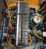
I checked continuity from the transistor solder connections to the heatsink and there is infinite resistance. As you can see it's a tight package into an old 70's Kenwood receiver chassis. Everything was working perfectly and it sounded great but of course I couldn't leave well enough alone.
Signal gnd and chassis gnd are isolated as they should be. The schematic may have some discrepencies due to undocumented revisions. I redrew this from a barely legible one. The quiescent current is set by measuring the voltage across R22-R23. It would seem Q12 is slowly being biased on since I am seeing a -DC on the output but not understanding how that can be and still the quiescent current reads normal.
Unfortunately I don't have an o-scope so my troubleshooting ability is limited. My knowledge level being the other limitation.
Attachments

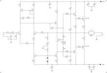
Q1 and Q4 must be matched, they correct for DC offset. A defect with Q8 may cause offset issues as well. Make sure your signal ground connects to the power supply ground.
Member
Joined 2009
Paid Member
I'm wondering if you have some damage to a transistor that is isn't visible but has affected it's behaviour ?
And 'wobbly' dc levels and hum can be an indirect indicator of parasitic h.f. oscillations.
And 'wobbly' dc levels and hum can be an indirect indicator of parasitic h.f. oscillations.
Yeah, weird things can happen to a transistor that doesn't include a total failure. That's why on a multi-output amplifier you change them all on that channel. Reverse E-B breakdown does nasty things if it doesn't kill the part. Beta can change and they may well get noisy.
That sounds more like the problem is on the other side of the circuit, Q11 and on back. It can't force the output back up toward ground, hence no crazy- high idle current. Measure Q11's VBE and see what you get.It would seem Q12 is slowly being biased on since I am seeing a -DC on the output but not understanding how that can be and still the quiescent current reads normal.
Going back to the fact that both channels are behaving similarly, you need to look for a common cause. It really doesn't sound like a problem on the board(s) -- how could both simultaneously exhibit the same problem if it's board-related? Seems pretty unlikely. Where did you measure the positive supply voltage? At the PSU? On the amp boards? It does suggest your boards may not be getting +40V to them. Got any fuses in the power supplly lines?
Just another possibility. I note that the amplifiers just have two ground connections, one for the input diff-pair, and one which serves as both the AC ground for the feedback, and also to run the CCS. If that ground connection to the boards is open the base of Q1 will be pulled down close to -40V (via the connection thru D2/D1/R11). Q4 then would have about 80V minus the reverse-breakdown voltage of Q1's EB junction. across it. If that is higher than Q4's breakdown voltage I can see a current route that would then turn Q8 on and then eventually pull the base of Q12 low. Yet another hypothesis to test.
That was my feeling too. I was reading + and - 40v right at the amp connection but maybe there's ripple on one rail that I'm not able to see with a multimeter? I'll do some more investigating tomorrow when I have the time.Going back to the fact that both channels are behaving similarly, you need to look for a common cause. It really doesn't sound like a problem on the board(s) -- how could both simultaneously exhibit the same problem if it's board-related? Seems pretty unlikely.
I just ordered some.Get new mica and grease and see if the problem goes away.
Seems a long shot but it's the only thing I changed and the only thing I can think of, other than the PS, that would affect both amps.
The mica is 2mm thick and doesn't compress like silicone. There may be no DC continuity, but with an AC signal I could see a narrow enough gap acting like a capacitor and causing some weirdness.
That's the straw I'm clinging to at least.
Last edited:
The mica is 2mm thick and doesn't compress like silicone......
I stand corrected, the ones i ordered are.2mm thick.
The ones that came with the amp seemed much thicker.
The ones that came with the amp seemed much thicker.
Q11's VBE is .610v and Q12 is .630v. I will check Q9/10 and on back tonight when I have more time.Measure Q11's VBE and see what you get.
- Home
- Amplifiers
- Solid State
- MJL21193/94 replaced mica insulator with silicone and now a hum and DC