Dear all,
Working to bring a VOX Escort Bass 50 back to working condition and discovered this oscillation in the circuit that is a mystery to me.
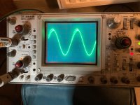
See schematic attached. See also picture of the waveform on the scope, taken at the point between C3 and C6. The oscillation that is added onto the audio signal has a frequency of about 10 Mhz. The oscillation is only present at low audio frequency (up to a few hundreds of Hz) and is impacted by all controls, especially volume and treble.
Have done quite some experimenting and found the oscillation to reduce when touching the housing (collector) of one of the output transistors (TR6) with the probe of the oscilloscope. Adding a 10nF capacitor between the collector and the chassis eliminates the oscillation. Yes, to the chassis and not to ground.
Quite familiar with tube amps but barely with solid state or opamp circuits. Any idea what is causing this ?
Your insights and comments are very welcome ! Thanks, Dirk
Working to bring a VOX Escort Bass 50 back to working condition and discovered this oscillation in the circuit that is a mystery to me.
See schematic attached. See also picture of the waveform on the scope, taken at the point between C3 and C6. The oscillation that is added onto the audio signal has a frequency of about 10 Mhz. The oscillation is only present at low audio frequency (up to a few hundreds of Hz) and is impacted by all controls, especially volume and treble.
Have done quite some experimenting and found the oscillation to reduce when touching the housing (collector) of one of the output transistors (TR6) with the probe of the oscilloscope. Adding a 10nF capacitor between the collector and the chassis eliminates the oscillation. Yes, to the chassis and not to ground.
Quite familiar with tube amps but barely with solid state or opamp circuits. Any idea what is causing this ?
Your insights and comments are very welcome ! Thanks, Dirk
Attachments

Probing at junction of C3 and C6 should be a benign spot to probe. I suspect you might be using a x1 scope probe. Be sure to use a x10 probe, as the large capacitance of a x10 probe can provoke opamp oscillation.
Connect scope probe ground clip to signal common. If using x10 probe doesn't stop oscillation, disconnect C16 to isolate output amp from end and try to establish where oscillation originates. Keep us posted.
Good luck.
Connect scope probe ground clip to signal common. If using x10 probe doesn't stop oscillation, disconnect C16 to isolate output amp from end and try to establish where oscillation originates. Keep us posted.
Good luck.
Thanks BSST. Yes, at 10MHz, the probe capacity is important. Have tested both using x1 and x10 but that did not have an impact. Also measured at different points in the opamp circuitry, they show the same oscillation. Will do the test with C16 disconnected, thanks for the suggestion !
At BSST : have disconnected C16, that does stop the oscillation completely.
At Loudthud : adding 100nF across C26 and C27 does not change the oscillation at all. There is no impact on the amplitude or lenght of the oscillation.
However, simply touching the housing of one of the power transistors, TR6, is enough to see a change in the amplitutde of the oscillation. Toucing TR7 has no effect whatsoever.
It is a mystery to me.
Next step is to determine if oscillation originates in PA section, or if in preamp section preceding C16. My guess is PA.
As a test, use C16 to bypass junction of R15,R16 to ground and try to localize source of oscillation. 0.1uF ceramic caps at opamp B+ and another similar cap at TR7 collector to ground would be good practice. "Ground" being circuit common. 10nF from TR6 collector is an interesting experiment, but not a recommended remedy. Keep us posted, please.
P.S. If amp is "opened up," ground bodies of volume and tone controls to keep them from being feedback antenna to preamp input.
Hello,
Not sure what you mean with "use C16 to bypass junction of R15,R16 to ground" ? Have reconnected C16. There is no oscillation at low volume or high frequency, hence need the signal to go through the amp.
The amp is out of the cabinet, but potentiometers are mounted on the chassis and the chassis is connected to both ground (common) and the earthing wire of the power cable.
Did use a 100nF film capacitor between TR7 collector and common. That does reduce the oscillation both in amplitude and length, but it is still there. Estimate that there is 30% reduction. At some setting of the volume potmeter, oscillation is gone. But at higher signal level it is still very present.
100nF between supply pin and ground at the IC with the 4 opamps does not have much of an impact, cannot see the difference on oscilloscope.
Connecting the same 100nF between C22 and chassis does eliminate the oscillation entirely. Does not work when connected to common / ground. Have checked the connections from ground to chassis, but these seem to be ok.
Common trace on the PCB is in two different sections. One is for almost the entire circuit and is connected to chassis at the input jack. There is a seperate shorter track that is used for the ouput stage, power transistors only. That is connected to chassis at the point between bridge rectifier and main filter capacitor.
PCB lay-out is the worst seen ever ....
Thanks !
Dirk
Good sluthing!
Is there a cap connecting circuit common to the chassis? That would be good practice and I didn't think to look for it.
Try installing that cap from circuit common to chassis instead of to C22. I suspect that may have the same happy result and would better satisfy my sensibilities. 😉
Is there a cap connecting circuit common to the chassis? That would be good practice and I didn't think to look for it.
Try installing that cap from circuit common to chassis instead of to C22. I suspect that may have the same happy result and would better satisfy my sensibilities. 😉
The common track on the PCB is split into two sections. Both sections are connected to the chassis with bolt and nut. One section is for the common for the power transistors and the other section is for the rest of the circuit. The latter is connected to the chassis at the input jack. The first one is connected to the chassis near the point where the bridge rectifier and the main filter capa are interconnected.
And yes, did test that. And althoug these are connected to the chassis, a 100nF between common near the power transistors and the chassis does significantly reduce the oscillation. But it does not eliminate it, reduction is only some 30% ...
Best Regards, Dirk
And yes, did test that. And althoug these are connected to the chassis, a 100nF between common near the power transistors and the chassis does significantly reduce the oscillation. But it does not eliminate it, reduction is only some 30% ...
Best Regards, Dirk
Base stoppers always springs to mind with these sorts of situations - though I'm not sure the symptoms totally fit in this case. Would it be possible to insert a low value resistor in series with the bases of the power transistors and also the driver transistors? Low enough not to affect normal working of the amplifier, and as close to device pins as possible?
Dear Keithj01, thank you for this. Also found this thread : https://www.diyaudio.com/community/...ry-for-output-stage-emitter-followers.368583/ The amp is returned to its owner, but if I ever see this one back, be sure I will test the insertion of base stoppers !! Again, many thanks, appreciated.
- Home
- Live Sound
- Instruments and Amps
- VOX Escort Bass 50 has 10 Mhz oscillation - why ?