Hi, folks,
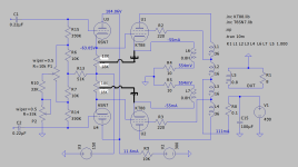
I have a direct-coupled 6SN7 cathode follower driver idea for push-pull KT88 / 60W output. Not made any THD simulation, just basic schematic/simulation in LTSpice with voltage/current/bias numbers. This unit requires (-150V) supply apart from HV B+/6.3V. Cathode follower solves one of the fundamental problems of fixed bias push-pull stages with RC coupling.
P2 33K trim potentiometer is for controlling bias voltage, P1 10k - balance.
Any ideas or suggestions are very welcome. LTSpice files attached as zip archive.
Thanks in advance.
Attachments

I”d regulate the -150V bus or add a zener to gnd from the left side of R13.
CCS underneath the CF”s is also nicer in my opinion.
Edit, there is a beefier pin compatible tube that would make a better cathode follower than 6sn7, the 6BX7
CCS underneath the CF”s is also nicer in my opinion.
Edit, there is a beefier pin compatible tube that would make a better cathode follower than 6sn7, the 6BX7
See morgan jones book building vacume tube amps.he has design of above.

Since the 15k resistor is a bit heavy load a ccs migth be a good idea but i would NOT recommend to stabilize the -150V UNLESS all other voltages are stabilized also.
If, for some (to me, unreasonable) reason something beefier than the 6sn7 is required the 6bl should be plenty, no need to toast the easy to drive KT88 grid with a 6bx7
If, for some (to me, unreasonable) reason something beefier than the 6sn7 is required the 6bl should be plenty, no need to toast the easy to drive KT88 grid with a 6bx7
Last edited:
Direct coupled cathode followers can work well for driving output tubes, I have at least four different amps that uses this concept. I'd look for something with more gm for the followers though, as common wisdom has it that high gm is an important factor in cathode followers.
Point taken about the regulation, does it have to be octal is the next question. ECC99 would perform better than the 6SN7 as a simple follower.
Ecc99 is a good choice.
I just notized, the opt cathode fb winding in your diagram will require additional swing , so you probable will need more than 150V negative PS even with a ccs.
I just notized, the opt cathode fb winding in your diagram will require additional swing , so you probable will need more than 150V negative PS even with a ccs.
Last edited:
6N6P could also be considered, pretty much the same thing as far as I know.
I once used a balanced 6N6P follower (with a center-tapped choke between the cathodes) to push a pair of triode wired 6L6Gs deep into class A2.
I once used a balanced 6N6P follower (with a center-tapped choke between the cathodes) to push a pair of triode wired 6L6Gs deep into class A2.
driving into A2 is no problem, but getting enough neg swing (without choke) could be, depending on the rest of the circuit and the avaiable power transformer heater winding(s). If there is only 1 winding feeding all heaters and a phase inverter with high pos voltage on the cathode you
migth need my secret weapon (a pc92 with Ufk 315/250V) to be able to increase the neg voltage enough to deal safely with all that (especially when using a resistance loaded cf)..
migth need my secret weapon (a pc92 with Ufk 315/250V) to be able to increase the neg voltage enough to deal safely with all that (especially when using a resistance loaded cf)..
Last edited:
My effort on this was published in AudioXpress Magazine May 2002.I have a direct-coupled 6SN7 cathode follower driver idea for push-pull KT88 / 60W output.
PP 6J5s as CFs driving the grids of PP KT88s or PP 6550s.
Twin Power Tubes form a bridge with twin HV PSs arranged so that the output is at ground (common).
As far as the signal is concerned the output tubes are in parallel, not in series as in a common PP circuit.
The resulting output impedance is one quarter of the regular circuit.
Three OPT setups are discussed. The front end is a common DIFF Amp, 6SL7/6SN7.
All here in this pdf.
Attachments
a pc92 with Ufk 315/250V)
The heater-cathode voltage rating can ideed become a very real problem when there are large voltage swings involved. P series tubes are usually better suited in this aspect, just like the PC92 you mentioned.
Yes, and there is also n other thing, if you need to swing high pp voltages it is good to not depend on the insulation properties of a folded heater alone. If possible, reduce the stress and swing the transformer heater windings with the signal fed through a resistor (at high frequencies it will work only partially because of the low pass formed with the TX-windinding capacitance,). With pp, you then need 2 seperated bottles anyway. And b.t.w., the pc92 has comparable high gm AND high mu, ideal for a cf.
And they are cheap
And they are cheap
Last edited:
I guess there's no need to regulate all supply voltages, but a regulated power tube screen supply is a demand then.Since the 15k resistor is a bit heavy load a ccs migth be a good idea but i would NOT recommend to stabilize the -150V UNLESS all other voltages are stabilized also.
Yes! Remember that the PC92 is just half a 12AT7 in a 7 pin envelope.And b.t.w., the pc92 has comparable high gm AND high mu, ideal for a cf.
Best regards!
My primary thoughts also, but according to the induction values given in the LTSpice schematics, it isn't a Unity Coupled design. Hence, drive signal requirements are increased, but not in the same way as in McIntosh's amplifiers.
Best regards!
Best regards!
Correct,
Correct, its not unity-coupled, its 3.9K output transformer with 12% CFB and 33 %UL.
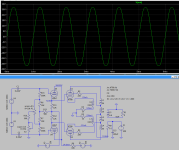
I have slightly changed resistor values, new schematic attached and looks like with ~115V RMS input it can deliver ~60W into 8 Ohm.
Each plate of the 6SN7 dual triode will dissipate roughly 1.9W, I think it should not be a problem.
Please correct if I'm something missing here. Thanks.
My primary thoughts also, but according to the induction values given in the LTSpice schematics, it isn't a Unity Coupled design.
Correct, its not unity-coupled, its 3.9K output transformer with 12% CFB and 33 %UL.
6SN7 heater should be probably biased at -100V. I have separate 6.3V output on power trafo to make separate supply for this CF 6SN7.The heater-cathode voltage rating can ideed become a very real problem when there are large voltage swings involved.
I have a box with 6N8S (=6SN7) already ;-) BTW, why you would consider beefier tube? Grid current of the KT88 is very low.Edit, there is a beefier pin compatible tube that would make a better cathode follower than 6sn7, the 6BX7
I have slightly changed resistor values, new schematic attached and looks like with ~115V RMS input it can deliver ~60W into 8 Ohm.
Each plate of the 6SN7 dual triode will dissipate roughly 1.9W, I think it should not be a problem.
Please correct if I'm something missing here. Thanks.
CorrectI guess there's no need to regulate all supply voltages, but a regulated power tube screen supply is a demand then.
- Home
- Amplifiers
- Tubes / Valves
- Q: 6SN7 Cathode Follower Driver Idea for PP KT88/60W