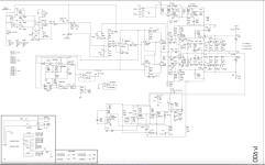
Hi, I'm currently servicing a PA amp, K.C.S PS-900 (it is a DAS P-900 on the inside, just rebranded outside).
EDIT after running several tests:
The relays don't click. There is one in the psu and one for each channel.
The PSU one tries to flick, there is a tiny movement but not enough to close the contact.
The ones on the output have no movement at all
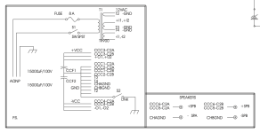
If I disconnect the PT (about 100V AC) from the rectifier/ relay board all relays work.
If I leave it connected and manually close the output relays they stay closed and I have sound...so I don't know what I'm supposed to look for.
It also had a hum on the output once relays were closed but that is pretty irrelevant for the moment I think.
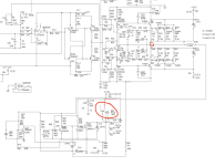
I replaced the amp board relay driver transistors and electrolytics on one board as it was cheap, i also checked the power transistors just to be sure. Amp side should be fine. And since it is a problem that interests both channels its definitely something happening above.
EDIT after running several tests:
The relays don't click. There is one in the psu and one for each channel.
The PSU one tries to flick, there is a tiny movement but not enough to close the contact.
The ones on the output have no movement at all
If I disconnect the PT (about 100V AC) from the rectifier/ relay board all relays work.
If I leave it connected and manually close the output relays they stay closed and I have sound...so I don't know what I'm supposed to look for.
It also had a hum on the output once relays were closed but that is pretty irrelevant for the moment I think.
I replaced the amp board relay driver transistors and electrolytics on one board as it was cheap, i also checked the power transistors just to be sure. Amp side should be fine. And since it is a problem that interests both channels its definitely something happening above.
Attachments
Last edited:
i may be wrong but if the relays are pitted from arcing and it's potentially got grounding issues it may be oscillating at high frequency
as PA amp it's likely been worked hard.
have you looked at caps yet? at this point there so many suspects or possibilities as to why it's misbehaving that without more data/measurement it's hard to advise you where to look or what to do/replace to fix it.
as to the relays it all depends on how they're made
How do I test it for oscillation? Would that affect the sound coming out or only the electrical operation of the amp itself? Becuse it sounds just fine...
All caps seem fine (visually). Where would you start diagnosing and what would you be looking for?
All caps seem fine (visually). Where would you start diagnosing and what would you be looking for?
And more importantly, what component triggers the relay / yellow led ON? because now that i have sound and relays switch i still have the protection led's on.. they just get a bit dimmer when the relays switch and it starts outputting sound.
Hum issue solved.. reflowed all solder joints so it might have just been a bad connection.
Hum issue solved.. reflowed all solder joints so it might have just been a bad connection.
for high frequency oscillation you need an oscilloscope, caps a good ESR tester.
the relays depending on just what is "designed in" could be as simple as a turn on delay, some will include some form of comparator in order to detect DC and inhibit operation(sorry without diving into the schematic details i can't say)
the relays depending on just what is "designed in" could be as simple as a turn on delay, some will include some form of comparator in order to detect DC and inhibit operation(sorry without diving into the schematic details i can't say)
Paused this repair for some time due to frustration. And although the more I study, the more I feel clueless, I'm giving it another shot.
I'm looking for a mentor but for the time being I've had no luck :/
I decided to momentarily ignore the humming problem and to focus on the relay not flicking on which bothers me much more.
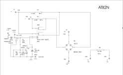
I looked at the relay driver circuit and while I don't really understand what each transistor is doing I am guessing that, as the amp is powered on, the circuit checks for possible DC/short circuit on the output, if none then 12V energise the relay coil, closes the contact and the amp is ready to output to speakers.
My first thoughts were:
Q: Are any of the transistors shorted? A: No
Q: is there DC on the output? A: No (-0.003VDC), on top of that if I manually close the relay contact it stays closed and I have sound coming out. So it seems more like an issue of the circuit not having the strength to turn on the relay.
This thought is also justified by the fact that if there actually was a problem the relay wouldn't stay open even if i tried to keep it closed manually.
Q: Why would this happen on both channels? the exact same issue. A: NO IDEA. Makes me think it might have nothing to do with the relay circuit at all since it influences both channels but I'm clueless.
So the help I need now is:
Could it be the relay circuit? How do I diagnose it?
Could it be faulty driver transistors (2N4401, MPSA13)?
Why would the relay not close on its own, but stay closed after I manually close it?
Where would the 12V supply come from to close the relay and what determines if relay is on or off?
I'm looking for a mentor but for the time being I've had no luck :/
I decided to momentarily ignore the humming problem and to focus on the relay not flicking on which bothers me much more.
I looked at the relay driver circuit and while I don't really understand what each transistor is doing I am guessing that, as the amp is powered on, the circuit checks for possible DC/short circuit on the output, if none then 12V energise the relay coil, closes the contact and the amp is ready to output to speakers.
My first thoughts were:
Q: Are any of the transistors shorted? A: No
Q: is there DC on the output? A: No (-0.003VDC), on top of that if I manually close the relay contact it stays closed and I have sound coming out. So it seems more like an issue of the circuit not having the strength to turn on the relay.
This thought is also justified by the fact that if there actually was a problem the relay wouldn't stay open even if i tried to keep it closed manually.
Q: Why would this happen on both channels? the exact same issue. A: NO IDEA. Makes me think it might have nothing to do with the relay circuit at all since it influences both channels but I'm clueless.
So the help I need now is:
Could it be the relay circuit? How do I diagnose it?
Could it be faulty driver transistors (2N4401, MPSA13)?
Why would the relay not close on its own, but stay closed after I manually close it?
Where would the 12V supply come from to close the relay and what determines if relay is on or off?
Attachments
looking for "shorts" is good but finding things that are "open" is sometimes harder, with semi-conductors opens are far less likely but still possible.Q: Are any of the transistors shorted? A: No
with power off doing continuity checks between key points in the circuit can verify that things should be going where they are meant to, opens means trouble and it could be as simple as cracked solder joints to open via's on the PCB.
I'm at the point where I am measuring all passive components to make sure they have the right values, so I'll also check for continuities.
What I'm more perplexed about is the fact that both channels have the same issue, but it's separate boards and separate relay driver circuits.
So what do they have in common? 12V to operate the relay and what else?
What I'm more perplexed about is the fact that both channels have the same issue, but it's separate boards and separate relay driver circuits.
So what do they have in common? 12V to operate the relay and what else?
well as i don't have first hand knowledge of the amp your working on my advice may not be useful.
without the full schematic to see what's tied to where it seems there's several connections and conditions that need to be satisfied before the relay closes and allows output and yes the fact that both channels exhibit the same behavior has me thinking the same way, finding something common to both but that may be overlooking that the design of the protection circuit would disable both channels depending on the fault that is detected.
is there any shared connections between the two protect circuits?
i would try to get one channel working before worrying about the fact that it's both.
Do you have a DVM? The place to start is by measuring the power supply voltages and see if they are right comparing to the schematic. You said that you could close the relay manually and it then stays closed. That's not normal. Would have to mean that there is some voltage on the coil. But it may not be full voltage. Anyway measure power supply.
I have a dim bulb connected and that drastically drops the mains voltage.
Before i disconnect it, do you think it is normal or too bright? Its a 100w bulb.
Also the schematic does not specify voltages which is annoying.
Before i disconnect it, do you think it is normal or too bright? Its a 100w bulb.
Also the schematic does not specify voltages which is annoying.
Attachments


Last edited:
ah so there is a current limiter involved. what is the Max voltage on your variac? so long as you monitor the AC input voltage bumping up the input voltage to see if the relays pull in shouldn't be a problem.
i found an old waterbed loom where i have four sockets in parallel so adjusting my current limit is as easy as turning on or off the different wattage lamps i have in the sockets.
i found an old waterbed loom where i have four sockets in parallel so adjusting my current limit is as easy as turning on or off the different wattage lamps i have in the sockets.
If I disconnect PT secondary (~100V) from the rectifier board which also has a relay, all relays flick on normally.
If PT is connected, rectifier board relay slightly moves but isn't able to close the contact.
Whats up with that?
If PT is connected, rectifier board relay slightly moves but isn't able to close the contact.
Whats up with that?
no not really and being that it's a class H amp not sure what nominal draw would be.Before i disconnect it, do you think it is normal or too bright? Its a 100w bulb.
i would have to see what the connections and loads are.Whats up with that?
because it's currently being current limited there's not enough juice to pull in the relays and supply the loads.
Still not fixed but I noticed something strange.
Schematic for the rectifier-relay shows MPSA13 transistor. The board has a BC283C mounted in it.
I know nothing about transistors but the main difference between the two is that MPSA13 withstands collector current of 300mA and higher voltages, BC283C only 100mA.
It's a 12V 140 Ohm coil so it passes 80mA so it's within it's limits, but is that the only factor to take into account? Or should that transistor not be mounted in there at all? I can't tell if it was factory installed or replaced by someone.
Also the emitter and collector legs are reversed between the two but it was correctly mounted in the pcb.
So could the "weaker" BC283C be the reason the relay doesn't move when 100V are applied to the rectifier?
Also whats the point of the psu relay In the first place? it bypasses 8W 12 Ohm resistors but why are they there?
likely to limit inrush current at start upAlso whats the point of the psu relay In the first place? it bypasses 8W 12 Ohm resistors but why are they there?
two different transistors the MPSA is a darlington so yes quite likely.So could the "weaker" BC283C be the reason the relay doesn't move when 100V are applied to the rectifier?
Last edited:
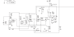
Another thing I don't understand is why is there an AC and a DC supply and what's the point of having them connected to each other after the 12VDC goes through the diode? 12vdc to close the relay but 16vac i don't understand

sorry not the best at explaining circuit theory and without the overall schematic to see where the 16 VDC comes from or what it's polarity is i'm not certain i understand it
my low ball understanding of this is a time delayed turn on.
i would check C1 and C2 and you did say Q1 may have been replaced,no?
my low ball understanding of this is a time delayed turn on.
i would check C1 and C2 and you did say Q1 may have been replaced,no?
- Home
- Amplifiers
- Solid State
- Hum & Protection Diagnosis advice - D.A.S. audio P 900 PA amplifier - preamp board issue