I designed and built this low power amplifier to drive an Usher S-520 two way speaker at my computer desk (near field, 2 feet speaker-to-ear).
With the bottom plate back on today, I am enjoying listening to a Kenny G Duotones CD.
I am attaching the following:
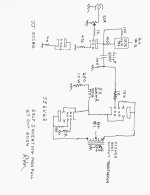
1 Amplifier Schematic
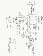
1 Power Supply Schematic
(Sorry for the sideways view, print them and rotate them; or play with software rotations and re-sizing).
2 pictures of the top of the amplifier showing the tip socket test points (it's nice to measure voltages without turning the amp upside down and removing the bottom plate).
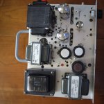
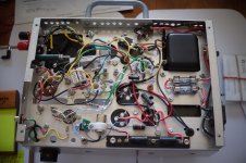
1 picture of the messy insides (the power transformer and chassis have been a good host to at least 4 different amplifier topologies).
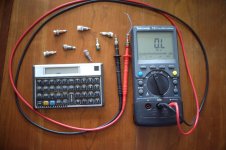
1 picture of tip socket test points, with, and without meter probes inserted.
I hope the schematics and pictures are self explanatory, if not, this thread has space for a few posts of questions.
With the bottom plate back on today, I am enjoying listening to a Kenny G Duotones CD.
I am attaching the following:
1 Amplifier Schematic
1 Power Supply Schematic
(Sorry for the sideways view, print them and rotate them; or play with software rotations and re-sizing).
2 pictures of the top of the amplifier showing the tip socket test points (it's nice to measure voltages without turning the amp upside down and removing the bottom plate).
1 picture of the messy insides (the power transformer and chassis have been a good host to at least 4 different amplifier topologies).
1 picture of tip socket test points, with, and without meter probes inserted.
I hope the schematics and pictures are self explanatory, if not, this thread has space for a few posts of questions.
Attachments


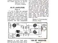
A very old circuit, the earliest I've seen is from about 1944, WW2 using PP 117L7GTs.
Many experimenters have built versions of this circuit including yours truly.
All my results were posted here on DIY. late 2016 & early 2017..
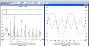
Best performer was using a choke in the tail, some of the measurement results at 7W.
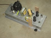
And a photo of the test mule.
Many experimenters have built versions of this circuit including yours truly.
All my results were posted here on DIY. late 2016 & early 2017..
Best performer was using a choke in the tail, some of the measurement results at 7W.
And a photo of the test mule.
Attachments
I like the use of an inductance as the LTP tail in the output stage.
Very nice looking amp.
I want to add one thing.
ECC82 has plate resistance about 7K. You don’t need to load it with a current source. A simple resistor is fine.
I want to add one thing.
ECC82 has plate resistance about 7K. You don’t need to load it with a current source. A simple resistor is fine.
Well, it depends on the required gain for that particular amplifier. Using a CCS maximises the gain. 12AU7 u is pretty low.ECC82 has plate resistance about 7K. You don’t need to load it with a current source. A simple resistor is fine.
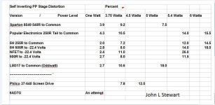
Summary of Performance Self Inverting Amplifiers Circuits
Conclusion, this circuit is not worth your time. Some versions use a Cascode Driver,
the 2nd triode is better used to form a normal inverter followed by regular PP final.
Many results for the curious still here on DIY.
Conclusion, this circuit is not worth your time. Some versions use a Cascode Driver,
the 2nd triode is better used to form a normal inverter followed by regular PP final.
Many results for the curious still here on DIY.
Attachments
A tube amp without global negative feedback, for me, it is definitely not for the performance. It is more like a musical instrument for a certain “tube” sound.Conclusion, this circuit is not worth your time. Some versions use a Cascode Driver,
the 2nd triode is better used to form a normal inverter followed by regular PP final.
If we only look at distortion figures then the whole valve amplifier business goes to the toilet, and one should buy a SS amp with 0.001% THD. Thankfully that's not the case.Summary of Performance Self Inverting Amplifiers Circuits
Conclusion, this circuit is not worth your time. Some versions use a Cascode Driver,
the 2nd triode is better used to form a normal inverter followed by regular PP final.
Many results for the curious still here on DIY.
For all the Fans of Distortion, this is the amplifier topology for you.
In this case the amp mule was running PP 6F6(M)s into a Hammond 125E.
The driver is a triode connected 6AU6.
The PS is a simple FW 5Y4G, about 300V.
I'm starting to think I'm in the wrong forum. Or maybe in the wrong time slot.
When I started out the World was analogue & when I retired at 78 we were mostly digital.
Most of my work was in leading edge test equipment where perfection was the order of the day.
Much of my time was in communications & power.
Distortion was something tested for in both fields Many folks are somewhat familiar with the dreaded 3rd harmonic.
But the power system in 3-phase has problems with the 5th & 7th too. And many others.
Guitar amps are now linear as possible. Distortion effects are produced by sometimes external or internal circuits.
One of my Grandsons has a PeeVee amp, PPP EL34s, it measures very good on the test bench & 110 Watts.
All on a MIL Grade PCB.
A while back I posted a circuit that can add 2nd H to the signal. By a controlled degree. Anybody see that??
Much to do, most of it is not here.
jxdking,
I had a good reason to use the IXYS CCS:
The ECC82 u = 20.
Note: No bypass cap across the 470 Ohm cathode resistor, Rk.
But the "missing" bypass cap raises the plate impedance according to u x Rk.
20 x 470 = 9,400 Ohms.
The new plate impedance is 7,700 + 9,400 = 17,100 Ohms
17,100 rp has to drive the CCS that is in parallel with the output tube's Rg, 100k.
Some would suggest that Rg can be much higher than 100k, yes it can . . .
But I wanted Rg, 100k, to effectively "swamp out" any grid current that might occur, when the peak signal swing puts g1 voltage at the tube's contact potential.
Many know that the g1 starts to draw a little grid current when g1 voltage is Very Very slightly positive versus the cathode voltage . . .
However, there Also is grid current when contact potential is reached.
I estimate the ECC82's contact potential to be somewhere between -0.5V or even -1.0V.
Because the self inverting pp output stage cathodes only see a choke and resistor in series, there is No bypass cap, (and self inverting can Not have a bypass cap).
Those who "hate to see" capacitors in their amplifiers, the only caps I use in this amplifier that see signal voltage, or that see signal current . . .
Are the coupling cap, and B+ # 1 cap, and B+ # 2 cap.
Those capacitor haters ought to be 1/2 way to Heaven, because of the low number of capacitors that see signal voltage or signal current.
(Do Not forget that as always . . . B+ filter capacitors Are in the signal path).
An interstage phase splitter could eliminate the coupling cap, and allow a change to the output stage cathodes.
But do not forget, B+ # 1 and B+ # 2 caps Are in the signal path.
I wanted to make a push pull amplifier that is as simple as any other push pull amplifier. I purposely decided against using:
an interstage inverting transformer; an Input inverting transformer followed by 2 triodes, a paraphase inverter, an LTP inverter, or a gain triode and concertina.
Make your own decisions about which topology you will use . . . and enjoy the near field listening sessions as much as I do.
The above tradeoffs were mine to make, when I designed the amplifier.
YDMV (Your Decisions May Vary).
Last edited:
The opinions of John Broskie & Alan Douglas attached.A tube amp without global negative feedback, for me, it is definitely not for the performance. It is more like a musical instrument for a certain “tube” sound.
Those with the ability to detect the sound change of a single resister or cap may disagree.
Attachments
Hi @6A3sUMMER ,
Right, the amp is lack of gain. The output stage is driven only by single end, which halfs the voltage gain farther. Another option is to add another stage with the 2nd half ECC82.
Right, the amp is lack of gain. The output stage is driven only by single end, which halfs the voltage gain farther. Another option is to add another stage with the 2nd half ECC82.
My amplifier design was specifically aimed at:
Low Power
Low Gain
CD player as the signal source, 2.1Vrms @ DAC full scale; 3V Peak @ DAC full scale.
Triode wired Beam Power tubes for medium damping factor, without using DHT, and without global, Schade, or any negative feedback from the output transformer.
Simplicity
Reliability
Ability to drive an Usher S-520 speaker for moderate volume @ 2 feet away (near-field listening).
The usefulness of this amplifier for anybody else, depends on the rest of the components of the system, such as loudspeaker, the acoustic environment, and the loudspeaker to listener distance.
$0.03
adjusted for inflation
I would prefer listening to Guy Lumbago & The Rolling Stones as the artists & techs doing the recording intended.A tube amp without global negative feedback, for me, it is definitely not for the performance. It is more like a musical instrument for a certain “tube” sound.
As little coloration of their performance as possible. Odd that some people want to stuff in a simple piece of gear
that the makers were trying to perfect.
To each his own . . .
Perhaps the solution is:
Get a very high paying job.
Purchase two single channel 100W Precision Laboratory Amplifiers, that can drive a load of 2 Ohms at any combination of LCR and voltage/current phase angle, and drive load impedances all the way up to an open circuit.
Then, quit reading and posting on diyAudio.
Tongue in Cheek
$0.04
Getting ready for when inflation really sky-rockets
...
Maybe you could recommend a set of speakers to pair with that amp? In the mean time I'm putting my house for sale 🙂Purchase two single channel 100W Precision Laboratory Amplifiers, that can drive a load of 2 Ohms at any combination of LCR and voltage/current phase angle, and drive load impedances all the way up to an open circuit.
You don’t need a high pay job. A $100 tpa3255 class d amp from Amazon can do that. Like this https://www.audiosciencereview.com/...ds/fosi-audio-v3-mono-amplifier-review.53474/Get a very high paying job.
Purchase two single channel 100W Precision Laboratory Amplifiers, that can drive a load of 2 Ohms at any combination of LCR and voltage/current phase angle, and drive load impedances all the way up to an open circuit.
Then, quit reading and posting on diyAudio.
It beats most solid state amps on specs. It is small enough to hide it behind the TV, and it runs cool.
I have both class D and solid state amps. Sometimes, I just want something different and I go back to tube.
Last edited:
jxdking,
There are few amplifiers that are as attractive as a pair of WE 212E mono-block single ended amplifiers.
The glow of the thoriated tungsten lights the ceiling, and the plates warm the room on a cool autumn day.
I was able to see and hear WE 212E amplifier decades ago, I never forgot that day.
It got me back to building vacuum tube amplifiers again.
The closest thing to the WE212E SE mono-blocks I would ever build, is a bit less aggressive, a similar amplifier with 845 output tubes.
$0.04
get ready for more inflation
- Home
- Amplifiers
- Tubes / Valves
- Self Inverting Push Pull 6V6S Mono-Block Amplifier with tip socket test points