I would like to build from scratch (not a kit) a solid state stereo amplifier and would like some suggestions for a tried & true design (if one exists). This will be a learning project for me.
Ideally the amp has the following attributes:
1) all discrete components, no opamps or integrated circuits
2) all components are readily available from reputable sources
3) can be wired point-to-point, circuit boards are not required
4) power output should be around 20 watts (or more) per channel
5) capacitor coupled output is preferable
6) class AB, I'm aware of the JLH class A but would like something more conventional
The above requirements are based on my interest in early solid state amplifiers, ca. 1960's. I own several from that era and would like to build something similar with modern components.
Last edited:

Check out this thread. It may check all your boxes and has superlative performance.
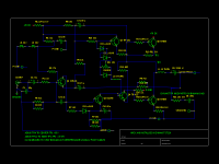
I never saw 3P compensated amplifier so I tried to build one. The basic design is come from the local forum's guru, Danhard. I made fine-tuning to adapt it to the real conditions. Three boards were built, the biggest problem was the correct placement of components and routing so as not to cause distortion degradation. The measured 1kHz/4R thd is under 0.0001%, the 10kHz/4R is about 0.0005%.

As you can seen the loopgain slope falls 60db/decadeView attachment 1044059

As you can seen the loopgain slope falls 60db/decadeView attachment 1044059
- LKA
- Replies: 159
- Forum: Solid State
Why not build the A40 by Nelson Pass? It is simple to build, quite conventional, yet sounds good. The PCB is available but not required, and parts can be substituted easily. It is Class A and needs heatsinks, but that should be an easy issue to solve.
Original A40 article
A40 parts substitution
Original A40 article
A40 parts substitution
This schematic is included with the QSPICE simulator install. It's discrete and class AB, but not sure how well it fits your other points.
I made this amplifier for test my home DIY speakers (two way TL).
D4 on component layout wrong polarity, in post #253 is corect componenet layout.
D4 on component layout wrong polarity, in post #253 is corect componenet layout.
- apexaudio
- Replies: 14,456
- Forum: Solid State
This amp meets all 7 criteria. https://www.diyaudio.com/forums/solid-state/236256-retro-amp-50w-single-supply-42.html My point to point build put out ~75 watts for 5 seconds on 8 ohm speakers. Page 42 shows my point to point boards on 1/16" Nema CE laminate. (micarta/textolite/garolite see mcmaster.com). The heatsinks were much bigger than post #4, something like a Pentium II heatsink. I have fans, PCAT power supply ones run at 7 VDC. Reason I did not use the PC board on page 1, too tall to fit in a dynaco ST120 chassis. I used 69 v 7 A power supply regulated from 72 v open circuit. NTE60 outputs were white box MJ15003 I believe from the datasheet. TIP31c/32c drivers were replaced in final version with MJE15028/29 for better highs. Q2 VAS could be MJE15028 also, D44R2 is a 20 mhz TO220 part. Output transistors and heat sense is on a remote heat sink from the driver board. L2 is close to the driver board to keep feedback from the 6" long wires to the heat sense diodes causing oscillation.
Sound is very good. When it was working properly I couldn't tell the difference at 1-75 w between this and a Peavey CS800s. I tucked the chassis behind the record tower to avoid the sound of the fans. Ran for 4 years up to 14 hours a day then I knocked a wire loose and when I replaced it now it hums some. Now using a Peavey M-2600 however that does not use fans so the RCA input cables can be 2 m instead of 4. C1 was increased to 150 pf ceramic to avoid picking up sports talk AM radio on the 4 m RCA cables. I live 2 miles from the transmitter.
Sound is very good. When it was working properly I couldn't tell the difference at 1-75 w between this and a Peavey CS800s. I tucked the chassis behind the record tower to avoid the sound of the fans. Ran for 4 years up to 14 hours a day then I knocked a wire loose and when I replaced it now it hums some. Now using a Peavey M-2600 however that does not use fans so the RCA input cables can be 2 m instead of 4. C1 was increased to 150 pf ceramic to avoid picking up sports talk AM radio on the 4 m RCA cables. I live 2 miles from the transmitter.
Attachments
Last edited:
Something breadboard or point to point might be LM1875
for simplicity.
Doesn't fit much to the 60's style.
People have modified the Classic Hitachi Mosfet to thermal track enhancement/vertical mosfets
or just a BJT output instead. Or Hunt down laterals/ use modern equivalents
Schematic from Hitachi Power Mos Fet Application Note
R4 often changed over to a 1ma current source instead, among other changes possible
Probably unbeatable simplicity for the performance.
hello guys...bsst , I like your suggest H ENG 60V.. 75Wrms / 4 ohm I presume......do you think it could drives 8ohm loads whitout any problems( with about 35/40Wrms )... Input wiring shielded ok for me too, why twisted pair?? it ' s should be a single ended signal ( with rca input , no differential input like XLR )...
nice day to everyone
Ros
nice day to everyone
Ros
I did that on garolite CE board. Both channels motorboated at about 5 cps. IMHO LM1875 requires the exact PCB traces shown in the datasheet to avoid motorboating.Something breadboard or point to point might be LM1875 for simplicity.
Doesn't fit much to the 60's style.
You can consider using TDA7265 Audio Amplifier. Here are the application circuits and other details:
https://www.theengineeringprojects....r-datasheet-pinout-features-applications.html
TDA7265 is a +25-watt class AB dual audio power stereo amplifier. This multi-watt package IC is carefully designed for high-quality audio power amplification applications. This device receives a low-input audio signal and amplifies it into a high-quality audio output.
- Home
- Amplifiers
- Solid State
- Seeking SCHEMATIC for a DIY Stereo Amplifier