Does anyone have a schematic for a Lanzar Optidrive 150 (Opti-150)? I got one with a couple components burned beyond recognition.
You've likely already realized that these boards are some of the worst/most fragile.
The attached diagram may be close.
If the resistors are the ones that lead from the output of the driver IC, they're not critical. The diagram attached shows them as 22 ohms driving 4 FETs. That value should be fine for the 150. If it has emitter-follower pairs as buffers, you can go a bit higher. 47 ohms were common in larger amps.
Install them raised slightly off of the board so they don't do damage if the amp fails again.
I have photos of a 150 if you have different resistors burned.
Attachments
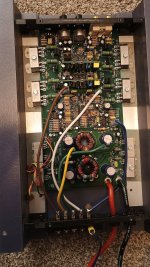
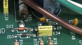
Thanks Perry. I haven't dug into it yet. Overall it looks pretty clean, other than this burned resistor in the middle, and this burned...ceramic cap(?)...near the power supply
Attachments

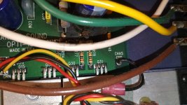

Great, thank you. Looks like a 104, 100,000pF, 0.1uF? Amp supposedly powers on, no sound. Maybe an easy one
Yes on the cap.
Check/clean the switches and if that's not it, check the muting circuit by confirming that the gate voltage is driving the JFETs off. .
Check/clean the switches and if that's not it, check the muting circuit by confirming that the gate voltage is driving the JFETs off. .
- Home
- General Interest
- Car Audio
- Lanzar Optidrive 150 schematic?