I'm considering adding secondary HV fuses to a Tubelab Simple SE project I'm building. The secondary winding voltage is 720VAC RMS and the current during normal operation should be about 170-200mA RMS. Assuming a fault, such as the rectifiers failing and turning into short circuits, the fault current would be less than 4A based on measurements of the PT's winding resistances and verified with some simulation.
According to the Valve Wizard's article[1], "secondary fuses can be of the glass (non HBC) type since fault currents are greatly limited by the transformer itself". This is also suggested by a Littlefuse document quoted in [2], although by now the document has been revised to only say that you should contact Littlefuse if considering using fuses above their voltage rating. I have contacted Littlefuse, and their response was essentially that, given my low interrupting current, I might be able to use a 250VAC fuse, but I should test.
So, I was wondering if any of you had any experience with using 250VAC fuses (either the glass or HBC types) at such voltages and had them interrupt the circuit during a fault without exploding. If possible, I'd rather use 5x20mm fuses and these only come in 250VAC ratings at 0.25A or so of operating current. Note that I'm considering the case of fusing each leg of the HV winding, as suggested in [1], and not the CT. In the latter case the voltage seen by the fuse would be half, so just 360VAC and the situation would be better.
[1] https://www.valvewizard.co.uk/fuses.html
[2] https://dalmura.com.au/static/Valve amp fusing.pdf
Of all the hundreds of stories here of shorted rectifiers and shorted input filters there are very few to none that tie those events to damage of the PT. A shorted PT would would blow the fuse on the primary. To consider doing it is one thing, but really needing them to save a PT when having a failure is not a disaster for a DIY amp, (classic vintage iron not included), is another.
isn't the result the same regardless of whether your amp blows the fuse or blows it up: circuit interrupted ...had them interrupt the circuit during a fault without exploding
Interesting. As I've said, I have not much experience on the matter. Douglas Self seems to advise for secondary fuses, sayingOf all the hundreds of stories here of shorted rectifiers and shorted input filters there are very few to none that tie those events to damage of the PT.
andDo not omit the secondary fuses; even in these modern times rectifiers do fail, and transformers are horribly expensive.
The valve wizard notes:Similarly, the mains transformer secondaries should also be fused. If this is omitted, a failure of the rectifi er will inevitably cause the mains transformer to burn out, and this could produce a safety hazard.
Of course Self talks in the context of solid state amplifiers, with different voltage and current levels and the valve wizard doesn't provide much explanation as to why a secondary fuse is necessary (or why it should be rated at 2-3 times the operating current).The primary fuse is mainly there to prevent serious faults which may lead to overheating, fire or shock hazards; it doesn't provide much protection for the components in the amp, even the power transformer.
If there are indeed no known instance of PT failure, or hardly none, ommiting them might indeed be preferable.
As far as the PT is concerned, yes. Not sure what the debris, or rather, in this context, shrapnel would do to nearby components, and such. I'm also not terribly fond of sudden loud bangs. 🙂isn't the result the same regardless of whether your amp blows the fuse or blows it up: circuit interrupted ...
Analyze the potential path of any shorted component. Does it have a direct path to ground? Tube rectifier, or SS bridge? Parts can fail without generating excess current. Just depends on the circuit type. Use components that have some ratings headroom and it will be reliable and simple.
Last edited:
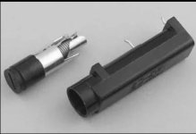
Then use enclosed fuse holders... Not sure what the debris, or rather, in this context, shrapnel would do to nearby components, and such. I'm also not terribly fond of sudden loud bangs.
or
simple pig tail fuse holders and heat shrink tubing
Attachments
I have seen the typical 250 volt 3AG fuse explode rather violently when exposed to a direct short on the secondary side of a 375-0-375 volt power transformer. This was provoked by a dumm blonde poking around with a cheap meter that had the red lead accidentally plugged into the 10 Amp jack (top) rather than the V-ohms-mA jack(middle). The fuse was wired in series with the CT on the HV winding. After that experience, I no longer fuse the secondary side of the transformer.
I have never seen a plate to plate short happen in a rectifier tube that had not been physically damaged. Plate to cathode shorts in a 5AR4 are rare but can happen. Plate to filament shorts in a DH rectifier like a 5U4, 5Y3, or 5R4 are NOT uncommon. The filament eventually goes open, usually at the turnround point leaving an unsupported end free to touch the plate. This will feed raw AC into the input filter cam making it rather unhappy. In a properly fused tube amp this SHOULD blow the primary fuse with no collateral damage. Often the filter cap will survive.
My exploding fuse and other experiments were done on a Tubelab SSE. I determined that a 1.6 amp slow blow fuse in the primary circuit was the bare minimum that would live on my 125 volt AC line in Florida. It was so close to the edge that an ocasional nearby lighning strike to the power lines would blow the fuse. I usually recommend a 2 amp fuse in 120 volt countries and a 1 amp fuse for 230 / 240 volt countries.
NEVER use an AC rated fuse on DC. They WILL violently explode and sometimes create a large fireball when they go due to a continuous arc that does not extinguish 100 or 120 times per second.
Attachments

Thanks for the feedback everybody.
I suppose going without secondaries might be better on the whole. I can always add them later, using inline fuse holders in the secondary wiring.
A fuse in series with the CT should have been exposed to 375VAC at most, right? And it still exploded? I wonder how that can be, since these fuses are generally rated for interrupting currents at least a couple orders of magnitude above the typical fault current for a shorted secondary. Many are rated in the thousands of amps. Since the energy of the arc inside the fuse is proportional to voltage times current, I'd expect the fuse to cope easily at twice the voltage and 100 times less current. I'm obviously missing something in the physics behind this.I have seen the typical 250 volt 3AG fuse explode rather violently when exposed to a direct short on the secondary side of a 375-0-375 volt power transformer. This was provoked by a dumm blonde poking around with a cheap meter that had the red lead accidentally plugged into the 10 Amp jack (top) rather than the V-ohms-mA jack(middle). The fuse was wired in series with the CT on the HV winding. After that experience, I no longer fuse the secondary side of the transformer.
But if there's enough energy to rupture the glass or ceramic casing of the fuse, why would the fuse holder do much more than provide a bit more mass flying around inside the amp enclosure (or the room if the enclosure doesn't have a bottom panel)?Then use enclosed fuse holders
or
simple pig tail fuse holders and heat shrink tubing
I suppose going without secondaries might be better on the whole. I can always add them later, using inline fuse holders in the secondary wiring.
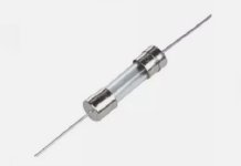
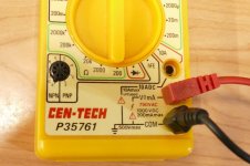
I used the meter in the picture to measure the DCR of one half of the secondary winding of the power transformer I commonly use at 62 ohms. The 115 volt primary winding is about 2 ohms, probably a bit less due to the resistance in the cheap meter leads. This puts the short circuit current in the 6 amp range for the few milliseconds it takes to vaporize the thin metal strip inside the glass fuse. This can create a very short pulse containing about 2 KILOWATTS of energy, quite a bit more if the short happened to occur at the peak of the AC half cycle. Odds are that the short occurred at a lower power point in the AC cycle, which is why sometimes things explode, sometimes they don't. DC is constant and once the short vaporizes the thin strip an arc can start through the cloud of vaporized metal. With no zero crossing to quench the arc, an explosion is likely. There are some sand filled fuses that do not explode unless subjected to something extreme like being zapped with a cardiac defibrillator, in which case you get a real big bang!
I tend to use generic fuses obtained from surplus houses with unknown specs. As mentioned, the bang created by an exploding fuse can usually be contained in a piece of heat shrink, but powdered glass can still be dispersed.
I did find some 500 mA fuses with ratings that would indicate that they are suitable for use on 500+ VAC at hundreds of amps, but they are several dollars each. I have never tried any of these.
Still, even a small 5x20mm 250VAC glass fuse, is rated for an interrupting current of 35A and above (based on a cursory look at Littlefuse datasheets). This would similarly result in a peak power of above 8kW, yet the fuse is supposed to stay intact. That's what leads me to assume there must be something more to it than just the dissipated power.This puts the short circuit current in the 6 amp range for the few milliseconds it takes to vaporize the thin metal strip inside the glass fuse. This can create a very short pulse containing about 2 KILOWATTS of energy, quite a bit more if the short happened to occur at the peak of the AC half cycle.
PSUD2 with 375-0-375 and 76 ohm effective half-winding shows a 6Apk through the CT, so about 4.1Arms, assuming the short was after the rectifier diodes (ie. trying to measure DCV with the DMM, rather than say across a half-winding to measure Vac). But initially all the voltage is dropped across each half-winding alternately, as any bolted short would have a relatively low resistance compared to the half-winding. So the fuse only starts to see a rising voltage as it starts to melt then arc, and the arc itself has a dynamic voltage that finally reaches 375Vrms when the arc current has fallen to nominally zero.
Two significant unknowns are the actual fuse used (ie. make/model/ratings/compliances), and the leakage inductance of a secondary half-winding. I'd suggest not trying to align the performance of an unknown fuse with a datasheet, or certain compliances, or some concept of what the fuse may do with respect to breaking glass. Also the leakage inductance of the winding may well introduce a significant voltage drop during the dynamic arcing phase when current may be changing rapidly (and not following a half-sine shape), and that is not modeled in PSUD2.
Given a nominal 6Apk, if the fuse was say 0.4A (just a guess), then that is circa 10x over-current (based on rms value). Typical UL compliant fuses used in USA don't have a specified operate time for anything over 2x over-current, so it is just a guess as to how many half-cycles the fuse element could remain conductive. If the fuse was subjected to more than 10x rms over-current, then the fuse likely follows an I2t performance behaviour, and likely arcs within a half-mains cycle.
So perhaps better to not bandy around kW dissipation levels, as that really has no meaning.
My innitial oops moment was a direct short from one of the plate pins on a 5AR4 to ground with an older Allied Electronics 6K7VG power transformer which is made by Hammond and similar to a 274BX. The fuse was a 1/2 amp, of unknown specs. It was one of those "100 1/2 amp fuses for a few bucks" bags full from All Electronics or Electronic Goldmine many years ago. I ditched the secondary side fuse and went with a 1.6 amp slow blow on the primary. The SSE lived a long issue free life. I sold it a couple years ago at the Dayton Hamfest and the new owner confirmed that it is still alive and well at the Hamfest last May.
Every application is different and there is usually a "proper" fuse choice for most applications, though they are not always chosen. Cheap fuses can and DO explode in the wrong application.
Every application is different and there is usually a "proper" fuse choice for most applications, though they are not always chosen. Cheap fuses can and DO explode in the wrong application.
- Home
- Amplifiers
- Tubes / Valves
- Secondary fuse voltage rating