Hi Gang,
I purchase a Diamond Audio D7401 that had been "repaired" by someone before I got it, he bench tested it and it was fine before it shipped. It's taken me ages to get this thing installed so I'm not looking to lean on the PO for help..
The amp does power up and "work" but if you put any real gain to the input it starts what seems like clipping and it always sounds distorted.
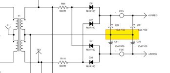
So I found the attached schematic on the internet which does appear to match my amplifier. First thing I did was check rail voltages, 15V supply and "Aux supply". I have about 64VDC at the rails and the 15v supply looks ok too. The mystery to me is this Aux power situation, which is where I think the problem may be, because I have +64v roughly and -72v so there's a large imbalance. Looking at the regulator in the diagrams if my understanding is correct this should be +/- 5V??? They're calling out 7805t and 7905t regulators.
Am I correct? I may be completely misunderstanding things.
Thanks for any help!
I purchase a Diamond Audio D7401 that had been "repaired" by someone before I got it, he bench tested it and it was fine before it shipped. It's taken me ages to get this thing installed so I'm not looking to lean on the PO for help..
The amp does power up and "work" but if you put any real gain to the input it starts what seems like clipping and it always sounds distorted.
So I found the attached schematic on the internet which does appear to match my amplifier. First thing I did was check rail voltages, 15V supply and "Aux supply". I have about 64VDC at the rails and the 15v supply looks ok too. The mystery to me is this Aux power situation, which is where I think the problem may be, because I have +64v roughly and -72v so there's a large imbalance. Looking at the regulator in the diagrams if my understanding is correct this should be +/- 5V??? They're calling out 7805t and 7905t regulators.
Am I correct? I may be completely misunderstanding things.
Thanks for any help!
Attachments
No, and that's why I assumed I was measuring incorrectly. If you don't mind, where should I be grabbing ground? I see two different ground markers in the prints now that you mention it.
EDIT - Looking again I was able to measure;
5V at the -rail
.5v at the +rail
Thank you!
EDIT - Looking again I was able to measure;
5V at the -rail
.5v at the +rail
Thank you!
Last edited:
Measuring across D23 and D15 respectively gives me 5V on the negative aux rail and .5 on the positive aux rail.
What is the aux power for? My meter went dead before I could do any further testing of course!
What is the aux power for? My meter went dead before I could do any further testing of course!
It's a driver supply voltage that allows the audio output to be fully driven to the rail voltage. Without it, the common collector output configuration can't drive fully to the rails. Some with this configuration have driver supply and some do not.
Ok this definitely matches my symptoms thank you for the education! I'll see if I can figure out the culprit and report back. I'm seeing quite a few potentially cracked solder joints so I'll start there.
Okay so I looked again. I may be doing this wrong.
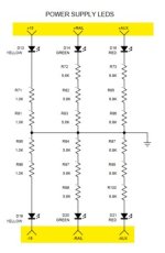
Attached is where I just measured the rails from, I get +/-65V or very close. Measuring auxillary power from there gives me +66 and -69.94 I guess I should have stated I am measuring these at the string of resistors/LED's in the center of the board.
Attached is where I just measured the rails from, I get +/-65V or very close. Measuring auxillary power from there gives me +66 and -69.94 I guess I should have stated I am measuring these at the string of resistors/LED's in the center of the board.
Attachments
Black probe on the yellow ground. You should read 5v greater than each rail on the aux out.
From the ground terminal for each regulator (black probe), you should read +5v for the +aux and -5v for the -aux.
From the ground terminal for each regulator (black probe), you should read +5v for the +aux and -5v for the -aux.
Okay I was doing it right just wasn't 100%, and wanted to clarify.
I'm definitely missing my aux 5v on the + side. U1 doesn't seem to be outputting anything across pins 2/3. Pin configuration is different on U9 (neg aux side) and I do get 5v across pins 1/3.
I'm definitely missing my aux 5v on the + side. U1 doesn't seem to be outputting anything across pins 2/3. Pin configuration is different on U9 (neg aux side) and I do get 5v across pins 1/3.
I see where you're going with this. I have not fully disassembled the amp yet, I will do that tonight after the kids go to bed. I'd attempt to heat the leg from the top and remove it but someone's already lifted some traces on this board so I want to be careful.
Thanks Perry!
Thanks Perry!
Okay leg cut and still no 5v present. Pin 1 to transformer CT is 66.11 and pin 2 is 64.96 and pin 3 is 65.58. Measure .56v between 2/3. Seems like the regulator is dead?
I just measured unregulated voltage from transformer CT and they're very different for FB5/FB6 (unregulated +/-)
FB5 - 66.14v
FB6 - -78.63V
FB5 - 66.14v
FB6 - -78.63V
- Home
- General Interest
- Car Audio
- Diamond Audio D7401 needs some help