Hi folks,
I'm looking for a simple dc protect and turn on delay circuit for a Nad 3020 preferably with pre existing pcb or at least gerbers, could anyone point me in the right direction or have info on something they use? Usable tapping point for voltage is 30.5v
I'm looking for a simple dc protect and turn on delay circuit for a Nad 3020 preferably with pre existing pcb or at least gerbers, could anyone point me in the right direction or have info on something they use? Usable tapping point for voltage is 30.5v
What I'm familiar with is a protection circuit designed by Bob Cordell and described in a Burning Amp seminar: #49 Its description begins at about 23:20 in the video.
I think the design would be adaptable to your needs with very minimal changes, if any. Rick Savas (@rsavas) offers a kit of bare PCBs to implement the amp described in the video. You would need two of the protection PCBs from his kit. Perhaps he will sell them as a subset of his kit. You could contact him if this approach appeals to you.
Good luck!
Last edited:
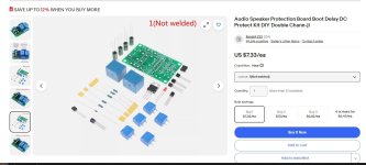
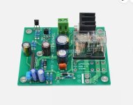
Just jumper the bridges on either the 12V BJT kit , or (below 2) , the uPC1237 24V omron kit.
First kit will run ac-dc 16-35V , second kit will run 27-37V. LM7824 will run up to 40V.
I'm using both kits. Second kit has current protect tap , goes on one amp emitter resistor.
Only 7-15$ for complete kits. I swap the caps out with panasonic/nichicon's.
OS
First kit will run ac-dc 16-35V , second kit will run 27-37V. LM7824 will run up to 40V.
I'm using both kits. Second kit has current protect tap , goes on one amp emitter resistor.
Only 7-15$ for complete kits. I swap the caps out with panasonic/nichicon's.
OS
Attachments
The simplest DC protection is placing a properly sized capacitor in the speaker line, say 2200uF at 35VDC. Why do you need a turn on delay?
The biggest 'problem' adding a protection pcb to the 3020 is simply finding a pcb / relay arrangement to fit the available space in the amp - but it's certainly possible. I added one to a 3020 a few years ago when I was just starting out with diy audio, using one of Rod Elliotts 'Project 33' pcbs + a couple of TE (RTD14012) sealed relays. It's not the most elegant by any means (I never did get back to tidying it up...), but it still works fine. 10 years later and I'd probably use a similar circuit but with solid-state relays, just as a smaller option.
I've looked at the diyaudio shop option, for more recent projects, but I can't bring myself to paying £37 ($48+) for the bare pcb. The additional shipping costs to UK are simply prohibitive, I suspect for many UK members.

I've looked at the diyaudio shop option, for more recent projects, but I can't bring myself to paying £37 ($48+) for the bare pcb. The additional shipping costs to UK are simply prohibitive, I suspect for many UK members.
Why not rebuild what you did ten years ago, it worked, why look for something different. Look here, it is cheap and probably nasty.
https://www.google.com/shopping/pro...&ved=0ahUKEwiftPGrx8SIAxV-WEEAHT_qBZUQ9pwGCAg
https://www.google.com/shopping/pro...&ved=0ahUKEwiftPGrx8SIAxV-WEEAHT_qBZUQ9pwGCAg
I'm not trying to improve on what I did 10 years ago, it works well as it is - it was just an example for 'Chris3521' (the OP) so he was aware of the size constraints within a 3020.
- Home
- Amplifiers
- Solid State
- Looking for a simple DC protection circuit for NAD 3020