In my quest to repurpose an MCS chassis, I would like to not have to buy a transformer. So I have available to me the existing 60Vac output, which I can feed into an existing rectifier board giving me +/- 40V DC.
I would like to re-regulate? the power down to +/- 18-24V.
I had thought that this would be an easy search, but I must not be typing in the correct terms. Ideally, this will be feeding an MM phono stage.
Given that this would seem to be a way to further separate the transformer from the system, I thought these things would be falling off trees. Am I missing something obvious here? Or, is this a fools errand to try to use the stuff I have?
The +/- 40 supply rails each have 3x12000 uf capacitors. Not sure how much capacitance would be needed after the voltage drop, but maybe some of these capacitors could be moved to the reduced/regulated circuit?
In an ideal world, these would be small enough that i could use this to individually feed the phono preamp on a fully separate circuit, and adjustable between +/-12 to 30V DC.
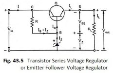
Just use this (below). Simple (NPN) Zener regulator with emitter follower. And a PNP for the negative.
Or use the P/N zener's to get to +/- 30 to 35VDC , then use LM317/337 for the adjustables. The LM's can only do 37V max.
This works , how I derive my +/- 12V supplies from big amp rail voltages (60 - 75V).
OS
Or use the P/N zener's to get to +/- 30 to 35VDC , then use LM317/337 for the adjustables. The LM's can only do 37V max.
This works , how I derive my +/- 12V supplies from big amp rail voltages (60 - 75V).
OS
Attachments
Using the LM's after the simple regulators is the best (and adequate) if your source is the crazy unregulated amp rails. Performance would
be stellar if the the source supply was not running a amp.
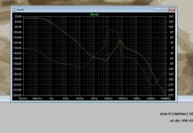
Here it is - a regulator regulating a regulator ..... 75-90db PSRR , not too bad.
OS
be stellar if the the source supply was not running a amp.
Here it is - a regulator regulating a regulator ..... 75-90db PSRR , not too bad.
OS
Attachments


Ok. I wish I had check my email more thoroughly than I had..or earlier. Because I had barely gotten past the identification of MJE105030/031 (the 032/033 is obsolete, according to digikey, but seems like they were only a higher voltage version?).
In the midst of frantically trying to teach myself KiCAD, I realized how little I knew. I was still trying to figure out how to calculate the heat dissipation in the zener....had I only looked here!
You saved me hours. Thanks!
The circuit makes a lot of sense to me, with the exception of the two diodes D1 & D3. I have no idea what they are doing, but I suspect that once I figure out KiCad it will be obvious.
Thank you very much for sharing the circuit!
You can use any 60V+ BJT P/N pair. Don't have to be the MJE's. Depending on your current draw , even TO-126 TTA/C004's will do.
TTA/C might even be able to do the whole 1A+ (of the LMs') without a heatsink. 10V drop of the pre-regulator = 1-2W.
My circuit just needs to run a few op-amps @ 50-100mA , no heatsinks - all is cool.
OS
TTA/C might even be able to do the whole 1A+ (of the LMs') without a heatsink. 10V drop of the pre-regulator = 1-2W.
My circuit just needs to run a few op-amps @ 50-100mA , no heatsinks - all is cool.
OS
So a reverse bias of the device will not cause failure. Bulletproof.The circuit makes a lot of sense to me, with the exception of the two diodes D1 & D3.
The Badger/Wolverine have additions like this. 0 failures.
Edit - they even use another diode reversed between ADJ and OUT of the LMxxx regulator.
Negative is easy - just reverse all the diodes.
OS
Thanks much. This has given me a great starting point to try to (a) hook things up, and (b) try to understand this a lot better.
another very similar solution:Simple (NPN) Zener regulator with emitter follower.
https://sound-au.com/project142.htm
or the pre-regulator for 317/337:
https://sound-au.com/project102.htm
Thanks for this as well.
Is there any benefit in rectifying the AC prior to this approach? My original thinking was that my existing schottky rectifier would provide a much more stable supply, but it does take up real estate, esp. with all the capacitors. But I already have the chips and heatsinks..
Or, is this just overkill?
Would doing so make adding a small 10-30W amp circuit feasible, if it were running off a separate LM regulated circuit, with 12000uf or so, or is interference in the ground signal make this a non starter? I am thinking something like my old NAD system, with jumpers in the back, so it could run as pure preamp, or as a modest system on its own.
- Home
- Amplifiers
- Solid State
- DC-DC voltage reduction/regulation circuit