Hello All,
Briefly, the problem is, when both the input and output grounds of a QA401 are connected to an amplifier, there is more 60-cycle related noise than if only one of these grounds is connected.
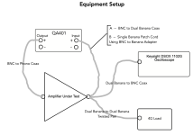
The first attachment shows the equipment setup I am using. Note that the connection between the QA401 Input and the amplifier output is either A or B. All other connections remain as shown, except when measuring the amplifier with a shorted input, so no connection to the QA401’s input is used.
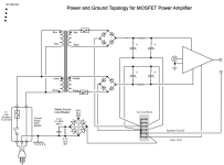
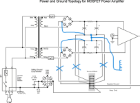
The second attachment shows the amplifier’s grounding topology.
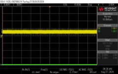
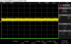
The third attachment shows the amplifier’s output with a shorted input.
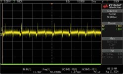
The fourth attachment shows the amplifier’s output when connected using the “A” option.
The fifth attachment shows the amplifier’s output when connected using the “B” option.
These measurements were collected with an unpowered QA401. The results are the same if the QA401 is powered, except for a bit more white noise.
I tested the possibility that a ground loop might go through the DSO by disconnecting it and looking at the amplifier’s distortion spectrum.
The sixth and seventh attachments shows the distortion spectrum using the “A” and “B” options, respectively.
That is a lot of material, I hope someone can make sense of it for me.
Thanks in advance for any suggestions.
Cheers,
ceulrich
Briefly, the problem is, when both the input and output grounds of a QA401 are connected to an amplifier, there is more 60-cycle related noise than if only one of these grounds is connected.
The first attachment shows the equipment setup I am using. Note that the connection between the QA401 Input and the amplifier output is either A or B. All other connections remain as shown, except when measuring the amplifier with a shorted input, so no connection to the QA401’s input is used.
The second attachment shows the amplifier’s grounding topology.
The third attachment shows the amplifier’s output with a shorted input.
The fourth attachment shows the amplifier’s output when connected using the “A” option.
The fifth attachment shows the amplifier’s output when connected using the “B” option.
These measurements were collected with an unpowered QA401. The results are the same if the QA401 is powered, except for a bit more white noise.
I tested the possibility that a ground loop might go through the DSO by disconnecting it and looking at the amplifier’s distortion spectrum.
The sixth and seventh attachments shows the distortion spectrum using the “A” and “B” options, respectively.
That is a lot of material, I hope someone can make sense of it for me.
Thanks in advance for any suggestions.
Cheers,
ceulrich
Attachments
You should better ask Matt at : https://forum.quantasylum.com/t/about-the-qa401-category/16
when I use my QA401 there is no other instruments connected to the DUT
.
when I use my QA401 there is no other instruments connected to the DUT
.
Use differential in to the QA401. You are getting the ground leakage current from the amp mixed into the QA401 input. If you use differential in and the grounding necessary is alrady handled with the source connection it should be noise free. You can coinfirm this by connectiong both + and - in's together to the chassis ground on the amp. You should see no hum or other spurious signals. If you do it might also be from transformer radiation. Twist the +/- cables tightly together to reduce the magnetic field pickup.

Are all devices plugged in to the same power circuit? I’ve seen stuff on two different breakers have annoying hum issues.
Its leakage from power transformers or supplies. It only takes a 100 pF of coupling to get enough current to get significant hum.
Classic earth loop.
You need to remove earth connection to one of the devices connected.
Leave earth connected to chassis but disconnect zero volt line on amp from earth.
You need to remove earth connection to one of the devices connected.
Leave earth connected to chassis but disconnect zero volt line on amp from earth.
Thanks everyone for your comments.
Fabrice63, I have posted on that forum previously, and they are very helpful, but since I am pretty sure this is not a problem with the QA401 itself, but more of an application problem, I thought this forum is a better match.
1audio, I have made the differential measurement using the QA401, and that does clean up the power-line related noise. Some related background: Previously on this amp I used a Tirad transformer without gauss band. I replaced it with the current AnTek banded transformer. Power-line related noise was about the same.
Your suggestion to connect both + and – in’s together, I assume you are referring to the grounds on those inputs?
mdpaudio, Yes, all equipment using the same wall outlet.
nigelwright7557, with the DSO not connected (attachments 6 & 7), only the amplifier is connected to the power-line. The QA401 is running on laptop battery. You suggested - “disconnect zero-volt line on amp from earth.” I am not sure I understand. If you are referring to the ground symbol on the amp input as shown in the ground topology drawing, I may have mis led everyone. There is no wire going from the input ground connector to a ground point. The input ground connector goes directly to the ground on the amp circuit card.
The second attachment shows the amplifier’s grounding topology.
i would do that grounding differently, see attachment.
Attachments
Hello Ctrix, thanks for the comment.
If I were using large can capacitors, I would surely try that topology, unfortunately, I am using power supply boards from the DIY Store, and making a connection between the capacitors would be a challenge.
Maybe, you could suggest a different topology considering that fact?
Cheers,
ceulrich
If I were using large can capacitors, I would surely try that topology, unfortunately, I am using power supply boards from the DIY Store, and making a connection between the capacitors would be a challenge.
Maybe, you could suggest a different topology considering that fact?
Cheers,
ceulrich
Are all the terminal block connections joined in a common connection? Not the best arrangement.
Would you post pictures, or at least details of the modules you've purchased.
Check your wiring of the ground breaker bridge. It's not correct if schematic is representing as wired.
Would you post pictures, or at least details of the modules you've purchased.
Check your wiring of the ground breaker bridge. It's not correct if schematic is representing as wired.
Hello BSST, Thanks for your comments.
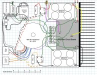
Attached is a drawing of the chassis layout. The amplifier is from Amps Lab (200W / 8 Ohm – MOSFET output stage), and as noted previously, the capacitor boards are from the DIY Store, and the transformer is from AnTek.
All terminal block connections are tied together using jumpers as shown. I understand that using this approach for a star ground is not the best. As I have worked this noise problem, I have been reduced the number of terminals in use, to what is shown in the chassis layout. Note, all wires carrying AC are twisted, as are the wires from the input connector to the amp card.
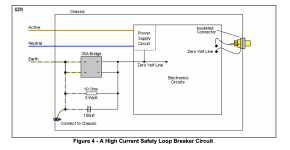
I am using Rod Elliott’s design for the ground loop breaker (see attachment) and I think I have applied it correctly. The schematic is representative of the actual hookup. If I have made a mistake here, please correct me.
Cheers,
ceulrich
Attached is a drawing of the chassis layout. The amplifier is from Amps Lab (200W / 8 Ohm – MOSFET output stage), and as noted previously, the capacitor boards are from the DIY Store, and the transformer is from AnTek.
All terminal block connections are tied together using jumpers as shown. I understand that using this approach for a star ground is not the best. As I have worked this noise problem, I have been reduced the number of terminals in use, to what is shown in the chassis layout. Note, all wires carrying AC are twisted, as are the wires from the input connector to the amp card.
I am using Rod Elliott’s design for the ground loop breaker (see attachment) and I think I have applied it correctly. The schematic is representative of the actual hookup. If I have made a mistake here, please correct me.
Cheers,
ceulrich
Attachments
Hi ceulrich,
Sorry for slow reply.
To address the ground loop breaker as depicted in first post 2nd photo, it appears that a wire passes West to East through the bridge and thus shorts across the diodes. I've used White-Out to rewire the bridge to make the schematic conform with the 2nd diagram post 11. Maybe this is related to the hum you're observing.
I've also shown revisions in accordance with @ctrix recommendations. I've noted large 120Hz hum currents driving the input caps, and much reduced currents in the 2nd cap in the supply. The routing should minimize hum introduced into the amps's signal ground.
The amp's input as illustrated in Chassis Layout.jpg above passes very near the positive bridge rectifier. It probably should be shielded and perhaps routed to avoid hum producers.
Good luck!
BSST, thanks for the very helpful comments.
It will take me a few of days to put the amp back on the test bench and make the modifications. I will report back.
ctrix, yes, it is a mono amp, and I used two cap boards, one for the positive rail, and one for the negative rail.
Cheers,
ceulrich
It will take me a few of days to put the amp back on the test bench and make the modifications. I will report back.
ctrix, yes, it is a mono amp, and I used two cap boards, one for the positive rail, and one for the negative rail.
Cheers,
ceulrich
Hello ctrix, yes, the capacitor symbols in the ground topology drawing represents a pair of capacitors wired in parallel in reality. I thought, for discussion purposes, the ground topology drawing would be an easy way to visualize the grounding. Maybe I was wrong, if there is interest or need, I can post the complete schematic.
Cheers,
ceulrich
Cheers,
ceulrich
First, ctrlx, I just noticed I have been spelling your handle incorrectly, sorry.
As it turned out, making the wiring change was quite simple since I used “Push-On” connectors. Modifying the ground loop breaker was a bit more complicated, but still not much work. Because of the way the bridge is cross-wired, I fail to see any actual difference between my original application and the revised version, except it looks more like Elliott’s. Maybe under fault conditions there is a real difference that I do not understand because I am not an engineer, however, I am willing to learn if someone will explain.
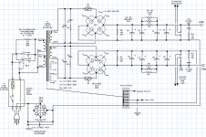
The first attachment shows the full power supply schematic.
Now for the measurements using the revised grounding topology:
The second attachment shows the amplifier’s output with a shorted input. Looks the same as the original grounding topology.
The third attachment shows the amplifier’s output when connected using the “A” option. There is clearly an improvement in both power-line related noise and background white noise, between the two grounding topologies.
The fourth attachment shows the amplifier’s output when connected using the “B” option. Same noise free signal as with the previous grounding topology.
The fifth and sixth attachments shows the distortion spectrum using the “A” and “B” options, respectively. The distortion spectrums confirm that the revised grounding topology does clean up the noise quite a bit. But does not solve the fundamental problem, that when both the input and output grounds of a QA401 are connected to an amplifier, there is more 60-cycle related noise than if only one of these grounds is connected. Remember, the QA401 is unpowered.
Cheers,
ceulrich
As it turned out, making the wiring change was quite simple since I used “Push-On” connectors. Modifying the ground loop breaker was a bit more complicated, but still not much work. Because of the way the bridge is cross-wired, I fail to see any actual difference between my original application and the revised version, except it looks more like Elliott’s. Maybe under fault conditions there is a real difference that I do not understand because I am not an engineer, however, I am willing to learn if someone will explain.
The first attachment shows the full power supply schematic.
Now for the measurements using the revised grounding topology:
The second attachment shows the amplifier’s output with a shorted input. Looks the same as the original grounding topology.
The third attachment shows the amplifier’s output when connected using the “A” option. There is clearly an improvement in both power-line related noise and background white noise, between the two grounding topologies.
The fourth attachment shows the amplifier’s output when connected using the “B” option. Same noise free signal as with the previous grounding topology.
The fifth and sixth attachments shows the distortion spectrum using the “A” and “B” options, respectively. The distortion spectrums confirm that the revised grounding topology does clean up the noise quite a bit. But does not solve the fundamental problem, that when both the input and output grounds of a QA401 are connected to an amplifier, there is more 60-cycle related noise than if only one of these grounds is connected. Remember, the QA401 is unpowered.
Cheers,
ceulrich
Attachments
Returning to Option A configuration and the corresponding jpg in the latest post:
Consider the configuration as shown in the original post. The big coaxial loop from QA401 to amp and back to QA401 is a receiving antenna for any magnetic hum fields passing through the enclosed area.
While observing scope, try dressing the routing of the cables so that input and output cables lie next to each other as closely as circumstances allow. The idea is to reduce the enclosed area to the extent possible. Be alert to any nearby powered equipment, as they are possible hum field transmitters--- maximize their distances to the extent possible. Any changes?
Other experiments that are more in the realm of sanity checks: turn off the power to the amp under test; change? Unplug amp from power source; change? Likely no hum observed, but sometimes there are surprises.
Another test not related to the QA401 loop: perform the compliment to the shorted input test above--- that is, look at noise with an open input. This assesses susceptibility to voltage fields coupling to the input wiring internal to the amp.
Good luck!
BSST, thanks for the continued interest.
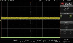
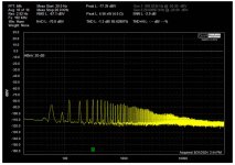
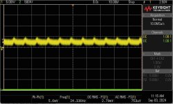
I did move the cables around and noted a rather large change in amplitude in power-line noise. I have been using BNC coax of different lengths which made the possible loop area much larger than necessary. The only other piece of equipment operating on the test bench is the DSO. The lowest amplitude noise was noted when I changed to matched-length twisted BNC coax cables (attachment 1).
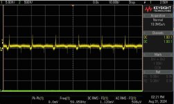
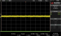
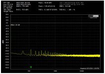
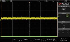
Looking at noise pick up by the twisted-pair going from the input connector to the amp board: Attachment 2 shows the noise with an open input. Attachment 3 shows the noise if that twisted-pair is disconnected at the amp. I do see some differences related to the input twisted-pair – a bit more white noise, and a very short positive-going spike. I have no frame of reference as to how important that is. It is a commercial product so the twist is very tight on that pair. Do you think a coax would make a significant difference?
If I power the amp down, the output goes to a straight line.
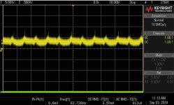
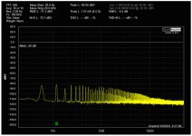
With the matched-length twisted BNC cables I was hoping that I would see an improvement in the distortion spectrum, but as shown in attachment 4, that is not the case.
Cheers,
ceulrich
I did move the cables around and noted a rather large change in amplitude in power-line noise. I have been using BNC coax of different lengths which made the possible loop area much larger than necessary. The only other piece of equipment operating on the test bench is the DSO. The lowest amplitude noise was noted when I changed to matched-length twisted BNC coax cables (attachment 1).
Looking at noise pick up by the twisted-pair going from the input connector to the amp board: Attachment 2 shows the noise with an open input. Attachment 3 shows the noise if that twisted-pair is disconnected at the amp. I do see some differences related to the input twisted-pair – a bit more white noise, and a very short positive-going spike. I have no frame of reference as to how important that is. It is a commercial product so the twist is very tight on that pair. Do you think a coax would make a significant difference?
If I power the amp down, the output goes to a straight line.
With the matched-length twisted BNC cables I was hoping that I would see an improvement in the distortion spectrum, but as shown in attachment 4, that is not the case.
Cheers,
ceulrich
Attachments
- Home
- Design & Build
- Equipment & Tools
- Help me understand a ground loop problem when using a QA401