ctrlx, thanks for the suggestion.
I agree, if I were building this amp today, I would not separate the cap boards for the two rails, and that would lead to a different arrangement of all components.
Cheers,
ceulrich
I agree, if I were building this amp today, I would not separate the cap boards for the two rails, and that would lead to a different arrangement of all components.
Cheers,
ceulrich
Sorry for the slow response, I have ben traveling. Let me clarify a bit more.1audio, I have made the differential measurement using the QA401, and that does clean up the power-line related noise. Some related background: Previously on this amp I used a Tirad transformer without gauss band. I replaced it with the current AnTek banded transformer. Power-line related noise was about the same.
Your suggestion to connect both + and – in’s together, I assume you are referring to the grounds on those inputs?
1) Get a baseline on the noise and CMRR of the analyzer- connect the hot leads of + and - together floating. You should have essentially the noise floor of the analyzer. If there is significant noise in this mode you could have a strong magnetic field or electostatic field. Lets presume it is noise free.
2) Take the differential and connect to the ground reference of the Device Under Test (DUT). Without a specific ground connection between the analyzer and the DUT there will be some potential. If its less than the common mode limit the noise level should not change with the + and - shorted together. Keep the grounds away for now.
3) connect a seperate ground wire from the QA401 (clip lead to a screw or ?). Then first check for excessive common mode as in #2. Then you can actually make a good differential measurement.
These are essentially the same instruction that the Tek 7A22 differential amp (https://w140.com/tekwiki/wiki/7A22) provides to get the best noise isolation. Once you have this down you can actually measure the noise voltages across ground connections.
1audio, thanks for taking the time to make the clarification.
Interestingly, I had one of those scopes and the dff preamp for many years.
Now I understand your comment to get a baseline noise reading with the differential inputs shorted.
I am not sure I understand step 2. “Take the differential and connect to the ground reference of the DUT”? Are you suggesting to connect both + and - to ground reference or just the +.
Cheers,
ceulrich
Not sure if this is the evaluation 1audio was suggesting, but here is some more data:
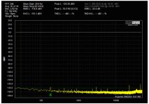
With the QA401 in differential mode and the two + and two - shorted, the background noise level is shown in attachment 1
The amplifier’s input was shorted.
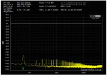
Now, connecting the two QA401’s positive inputs to the amplifiers negative output. The two QA401’s negative inputs were connected but otherwise floating. Attachment 2 shows the power-line noise spectrum on the amplifiers negative output.
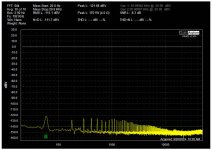
Maintaining those connections, attachment 3 shows the noise spectrum if a connection is made between the amplifier’s negative output to the QA401 ground. Clearly, the power-line related noise is reduced, but not by much.
Not sure what this tells me. At 60 Hz the amplitude is at -111dBV, with the added ground it is down to -121dBV. Can this really be the source of my problem?
Cheers,
ceulrich
With the QA401 in differential mode and the two + and two - shorted, the background noise level is shown in attachment 1
The amplifier’s input was shorted.
Now, connecting the two QA401’s positive inputs to the amplifiers negative output. The two QA401’s negative inputs were connected but otherwise floating. Attachment 2 shows the power-line noise spectrum on the amplifiers negative output.
Maintaining those connections, attachment 3 shows the noise spectrum if a connection is made between the amplifier’s negative output to the QA401 ground. Clearly, the power-line related noise is reduced, but not by much.
Not sure what this tells me. At 60 Hz the amplitude is at -111dBV, with the added ground it is down to -121dBV. Can this really be the source of my problem?
Cheers,
ceulrich
Attachments
It is cold and snowy in mid-Ohio, so I have a lot of time on my hands.
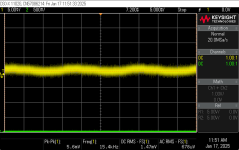
I wondered how much effect the spacing between the positive and negative rails of the power supply has on the observed 60 Hz related noise. The two rails of the diy Audio Power Supply PCBs are side-by-side, with essentially no distance between them. To approach that spacing in my amplifier the only option would be to stack the PCBs for the two rails. However, considering that the stacked boards will be fitted in a corner of the amplifier, access to the connections would be difficult because the inputs and outputs are on opposite ends of the boards, So, with the help of KICAD, I designed a capacitor PCB with inputs and outputs on the same end of the board, and with the same mounting footprint as the diyAudio boards. The first attachment shows the resulting stacked PCB module.
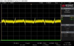
I installed that module, and repeated some of the measurements made back in Post #1. The second attachment shows an oscillograph of the amplifier’s output with the same measurement conditions used for the oscillograph in attachment #4 of Post #1. There is very little difference. So, separating the PCBs for the positive and negative power supply rails is not the source of the apparent ground loop problem.
As I continued to work this problem, I did stumble on the solution, rotating the transformer! The third attachment shows an oscillograph after rotating the transformer about 60 degrees. I had considered this the least probable cause, because previously I had a 500 VA transformer, without a flux band, installed in this amplifier, and I spent a lot of time checking for rotation effects, and found none. Go Figure!
So, did or do I have a ground loop problem or just a radiated-noise problem?
Cheers,
ceulrich
I wondered how much effect the spacing between the positive and negative rails of the power supply has on the observed 60 Hz related noise. The two rails of the diy Audio Power Supply PCBs are side-by-side, with essentially no distance between them. To approach that spacing in my amplifier the only option would be to stack the PCBs for the two rails. However, considering that the stacked boards will be fitted in a corner of the amplifier, access to the connections would be difficult because the inputs and outputs are on opposite ends of the boards, So, with the help of KICAD, I designed a capacitor PCB with inputs and outputs on the same end of the board, and with the same mounting footprint as the diyAudio boards. The first attachment shows the resulting stacked PCB module.
I installed that module, and repeated some of the measurements made back in Post #1. The second attachment shows an oscillograph of the amplifier’s output with the same measurement conditions used for the oscillograph in attachment #4 of Post #1. There is very little difference. So, separating the PCBs for the positive and negative power supply rails is not the source of the apparent ground loop problem.
As I continued to work this problem, I did stumble on the solution, rotating the transformer! The third attachment shows an oscillograph after rotating the transformer about 60 degrees. I had considered this the least probable cause, because previously I had a 500 VA transformer, without a flux band, installed in this amplifier, and I spent a lot of time checking for rotation effects, and found none. Go Figure!
So, did or do I have a ground loop problem or just a radiated-noise problem?
Cheers,
ceulrich
Attachments
The new transformers flux density is higher so more radiation. Thransformer vendors don't talk much about how hard the drive their magnetics but lower flux equals higher cost so these issues will crop up.
Not sure if this is helpful or not, but this is an article I used to have up on this site (when it still hosted articles) about what's happening with "ground noise" in unbalanced connections. The "fix" described constitutes a design change so probably not applicable here but still interesting (and it worked tremendously for me!).
The ground noise issue
The ground noise issue
Attachments
1audio – Thanks for that information. The 400VA transformer I am currently using is an AnTek, which I thought was a higher quality than the 500VA Triad I used originally.
bwasio – Thanks, I found your paper very instructive. As you said, it won’t help with my amplifier, but it helped me understand what is going on with ground loops.
Cheers,
ceulrich
bwasio – Thanks, I found your paper very instructive. As you said, it won’t help with my amplifier, but it helped me understand what is going on with ground loops.
Cheers,
ceulrich
- Home
- Design & Build
- Equipment & Tools
- Help me understand a ground loop problem when using a QA401