Hi all,
I got an Audible Illusions 3A with 120v power supply version. Now i would like to change to 220V power supply.
Does any of you have done it before or does any of you have the its PSU schematic diagram?

Thanks and regards,
I got an Audible Illusions 3A with 120v power supply version. Now i would like to change to 220V power supply.
Does any of you have done it before or does any of you have the its PSU schematic diagram?
Thanks and regards,
Hi. Maybe transformer has two primaries, whose are now connected in parralel, wire them in series and you get 220-240V version. Check all windings with ohmmeter, write all info, and use a step-down transformer 220-120V , and connect preamplifier through it, then measure all voltages.

Thanks, i need a PSU schematic diagram so i know how to pick an exact transformer for my need, like how many volts each of the output....without doing any measurement.
Hi, according to you, i should remove the transformer from the mainboard, put it in to 120V power supply, and measure the voltage out of each of the secondary coil to find the output voltages?
Schematics do not exist. You can try calling AI and speaking with Art about a replacement tranny.Hi all,
I got an Audible Illusions 3A with 120v power supply version. Now i would like to change to 220V power supply.
Does any of you have done it before or does any of you have the its PSU schematic diagram?
View attachment 1349072
Thanks and regards,
My pleasure. BTW, I have a good relationship with AI; if you need assistance I may be able to help getting the 240V tranny.
Hi, i just need to know the output voltages of the 120v transformers, so i can make one or buy one to replace it. Can you help?
Questions like this should always first be asked to the manufacturer before doing any action. This is the shortest path from A to B in many cases. Handy guys like found here have to guesstimate by looking at pictures while the manufacturer knows what he has made/designed.
The transformer on the picture seems to have only 120V primaries and many secondary windings but looks may be deceiving. The manufacturer can tell for sure. A 230V version will be an expensive one to have made and even if a member here gives the measured voltages you will not be sure what the intended voltages were by design. It will also probably/likely be more expensive than buying a 230V EU version (never choose a 220V version, mains voltages tend to go up not down) from the device producer. If it exists that is, it could be a US only device. Again something the manufacturer can tell. Therefor the advice wheezer gave seems most logical, affordable and efficient.
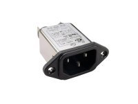
Advice is also to use PCB connectors and not solder wires directly to boards as the manufacturer did. Today that is considered plain bad practice for various reasons and no quality manufacturer does this today. How is one supposed to get the board out of the device made like this? Since the mains wiring is also too short you could consider using a Schurter IEC inlet with built filter (right current rated!) and benefit from the longer length and then have adequate length of wiring. Use 6.3 mm crimped faston connectors and don't make the same mistake by soldering wires. Clean power is a joy, no drawbacks.
Audible Illusions
7066 Commerce Circle
Pleasanton, CA 94588
(510) 463-9191
The transformer on the picture seems to have only 120V primaries and many secondary windings but looks may be deceiving. The manufacturer can tell for sure. A 230V version will be an expensive one to have made and even if a member here gives the measured voltages you will not be sure what the intended voltages were by design. It will also probably/likely be more expensive than buying a 230V EU version (never choose a 220V version, mains voltages tend to go up not down) from the device producer. If it exists that is, it could be a US only device. Again something the manufacturer can tell. Therefor the advice wheezer gave seems most logical, affordable and efficient.
Advice is also to use PCB connectors and not solder wires directly to boards as the manufacturer did. Today that is considered plain bad practice for various reasons and no quality manufacturer does this today. How is one supposed to get the board out of the device made like this? Since the mains wiring is also too short you could consider using a Schurter IEC inlet with built filter (right current rated!) and benefit from the longer length and then have adequate length of wiring. Use 6.3 mm crimped faston connectors and don't make the same mistake by soldering wires. Clean power is a joy, no drawbacks.
Audible Illusions
7066 Commerce Circle
Pleasanton, CA 94588
(510) 463-9191
Last edited:
Really appreciate, this preamp has separate power supply, and it has IEC inlet with the power supply. I'll do as you advised me to with PCB connectors . Many thanks.
Apparently they moved.
| Phone 386-676-2004 Business Office | Webmaster ml@audibleillusions.com |
| Mail PO Box 2505 Ormond Beach, FL 32175 USA | E-Mail info@audibleillusions.com sales@audibleillusions.com |
Yes I understood. That IEC inlet with built in EMI filter will give good results certainly with today's polluted mains voltage. Choose one with the same hole spacing. These do differ from brand to brand. If you know the drawn power to be below let's say 300W then choose a 3A version.
Attachments
Last edited:
In the simplest case, you can set a transformer in front of it. There are generally e.g.: 2 x 120 V : 1 x 240 Volt.
Thanks, i just don't want to have more equipment in my listening room, not enough space.
Please report here what the answers/results are. You will maybe help out someone else with the same question. The surprising answer may be that it does have 230V windings and only a few wires need to be rearranged (the PCB indicates that). Green to 6, yellow to 5 etc. That would be wonderful news, an efficient and affordable solution for you and interesting to know for us.
Thank you.
BTW USA companies tend to be safety freaks fearing death and destruction of their customers so make sure you tell them you are competent/certified. Of course only if you are competent or know someone that is. I recall ordering completely insulated click in modules at one manufacturer and the order was refused 🙂 Only after a written statement with signature I could order.
Last edited:
Experience has shown that the second primary winding with the same cable length as the one used would be found on the transformer. It could probably be fixed in the circuit board at "zero points".
Surely do.Please report here what the answers/results are. You will maybe help out someone else with the same question. The surprising answer may be that it does have 230V windings and only a few wires need to be rearranged (the PCB indicates that). Green to 6, yellow to 5 etc. That would be wonderful news, an efficient and affordable solution for you and interesting to know for us.
Thank you.
BTW USA companies tend to be safety freaks fearing death and destruction of their customers so make sure you tell them you are competent/certified. Of course only if you are competent or know someone that is. I recall ordering completely insulated click in modules at one manufacturer and the order was refused 🙂 Only after a written statement with signature I could order.
- Home
- Amplifiers
- Power Supplies
- Change power supply voltage for Audible Illusions 3A preamp