Hi All,
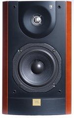
I just acquired a pair of JBL L20 (European model, made in Denmark), photo attached.
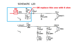
I would like to change the capacitors in the tweeter's crossover (schematics attached) to Jantzen capacitors but there are 2, C2 1uF in parallel with R1 3R9 resistor and C1 in series, now I want to use the Jantzen superior Z cap but the 6.8uf cost more than what I'm willing to spend so my idea is to get a 1uF superior Z cap and a Jantzen standard Z cap for the 6.8uF capacitor.
I would like to know please what's the reason for the 3R9 resistor in parallel with the 1uF cap?
why not just use 3R9 in series with 7.8uF (or 8uF) capacitor?
Thanks
I just acquired a pair of JBL L20 (European model, made in Denmark), photo attached.
I would like to change the capacitors in the tweeter's crossover (schematics attached) to Jantzen capacitors but there are 2, C2 1uF in parallel with R1 3R9 resistor and C1 in series, now I want to use the Jantzen superior Z cap but the 6.8uf cost more than what I'm willing to spend so my idea is to get a 1uF superior Z cap and a Jantzen standard Z cap for the 6.8uF capacitor.
I would like to know please what's the reason for the 3R9 resistor in parallel with the 1uF cap?
why not just use 3R9 in series with 7.8uF (or 8uF) capacitor?
Thanks
Attachments
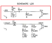

That's a high-pass filter circuit, as you know.
The high-pass filtering action results from using C1 and C2 as a coupling capacitor in series with the load. This T-type filter uses the inductance for a high-reactance choke across the line. In this way the higher-frequency components of the input voltage can develop very little voltage cross the series capacitance, allowing most of the voltage to be produced across the 3R9 resistor. The inductance across the line has higher reactance with increasing frequencies, allows the shunt impedance to be no lower than the value of the 3R9 resistor.
The high-pass filtering action results from using C1 and C2 as a coupling capacitor in series with the load. This T-type filter uses the inductance for a high-reactance choke across the line. In this way the higher-frequency components of the input voltage can develop very little voltage cross the series capacitance, allowing most of the voltage to be produced across the 3R9 resistor. The inductance across the line has higher reactance with increasing frequencies, allows the shunt impedance to be no lower than the value of the 3R9 resistor.
Duke58 thanks, but why not use one capacitor in series? Why split the capacitance and parallel just the 1uF with the resistor?
Which capacitor you are referring to?Because of the value of the capacitor, that's in the xo to lift the top end of the tweeter.
Thanks
The resistor is padding the tweeter down to match its level to the midwoofer. The 1u cap is added to bypass the the resistor at the very top of the tweeter range to lift its (presumably) falling response up there.
Edit: as to why not use 3R9 in series with 7u8, that would lower the crossover frequency of the tweeter filter (which would make it not match the midwoofer filter) and would not lift the tweeter response since the resistor would affect its response at all frequencies.
Edit: as to why not use 3R9 in series with 7u8, that would lower the crossover frequency of the tweeter filter (which would make it not match the midwoofer filter) and would not lift the tweeter response since the resistor would affect its response at all frequencies.
Last edited:
Exactly!The resistor is padding the tweeter down to match its level to the midwoofer. The 1u cap is added to bypass the the resistor at the very top of the tweeter range to lift its (presumably) falling response up there.
So if I understand correctly both of C1 and C2 capacitors quality (Jantzen superior Z vs standard Z) is equally important, correct?Edit: as to why not use 3R9 in series with 7u8, that would lower the crossover frequency of the tweeter filter (which would make it not match the midwoofer filter) and would not lift the tweeter response since the resistor would affect its response at all frequencies.
I'm in my 50's so I doubt I'd even hear what the 1u cap is doing (the frequency at which the cap reactance matches the resistor is ≈40 kHz, so the effect is going to be very subtle and well into the top octave). The 6u8 cap should have a comparatively more audible effect, depending on what type of cap is currently there.
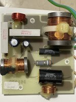
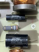
I've used Bennic XPP caps many times over the years and they are perfectly fine. I very much doubt anyone would hear a difference in a proper blind test against any other polypropylene cap no matter how expensive, except perhaps due to their actual values being different due to tolerance. IOW, I wouldn't bother changing them, but this is a controversial subject and others will strongly disagree, I'm sure.
On the other hand the two caps in the midwoofer filter seem to be non-polar electrolytics, and those I would definitely replace. If I'm not mistaken this model is around three decades old, so those caps could well be significantly degraded by now. Since the values are small I'd probably go with polypropylene, although C4 has only a small resistance in series (0R33 plus whatever L4 has) and it may well be that the ESR of the cap was accounted for in the design, so I might go with just a fresh non-polar electrolytic there.
On the other hand the two caps in the midwoofer filter seem to be non-polar electrolytics, and those I would definitely replace. If I'm not mistaken this model is around three decades old, so those caps could well be significantly degraded by now. Since the values are small I'd probably go with polypropylene, although C4 has only a small resistance in series (0R33 plus whatever L4 has) and it may well be that the ESR of the cap was accounted for in the design, so I might go with just a fresh non-polar electrolytic there.
Thank you all.
Another question, I noticed that the tweeter output is a little too high and unbalanced with the woofer output to my ears so I added a temporary 2.3 ohm (R0) resistor on the tweeter's input which solved the issue, I would like to know please if it would be better to replace the R1 3.9 ohm resistor with a 6 ohm resistor or just leave the R0 2.3 ohm in series with the tweeters input?
What is the effect on the tweeter's crossover frequency in the following 2 situations?
1. 2.3 ohm+3.9ohm (with the capacitor in parallel with just the 3.9ohm)
2. replace the 3.9ohm resistor with 6 ohm (capacitor in parallel with the 6 ohm)
Thanks
Attachments
by "directly on the tweeter" do you mean after the high pass filtering? after C1 capacitor in series?
Thanks
Thanks
When you add the resistor you move the xo frequency up, so you should increase the values of L and C to keep the original xo frequency.
Blue = original filter
Red = original filter +resistor
Black = filter in photo (the value of L & C are fictious because I used a generic SBA tweeter).


Blue = original filter
Red = original filter +resistor
Black = filter in photo (the value of L & C are fictious because I used a generic SBA tweeter).
Last edited:
When you add the resistor you move the xo frequency up, so you should increase the values of L and C to keep the original xo frequency.
That's why I said to use a voltage divider.
- Home
- Loudspeakers
- Multi-Way
- JBL L20 (European model) tweeter's crossover question