Hi all.
Recently bought a pair of these speakers. It became very clear that one tweeter was outputting at a small fraction of the other - mono white noise signals sent to the HF inputs showed this very clearly. Tested both tweeters by removing them and - carefully - wiring them straight to the amp's output, and they performed identically. Refitted them, and the same as before. Took the amp's speaker cable direct to the crossover's output to this dodgy tweeter, and it tweeted loudly as it should. So, a fault in the crossover.
No obvious dry or bad joints, all resistors tested to be correct values, and inductors tested for continuity. I have no way to test the caps, but none are looking 'faulty' - no leaks, no bulges. So, most likely a capacitor has gone faulty. No biggie - I will replace them all.
Q's - what type of poly capacitors should I choose? Any benefits from staying with what's there (round polys) or going flat-rectangle!
And, can anyone explain what's going on with the circuit? Why have two caps in parallel when one (larger) one would do? And, why have an electrolytic in parallel with a poly?
The schematic is mine, but I've rechecked it a few times. Thanks!
Last edited:
It is highly unlikely that one of the poly caps in the tweeter filter has gone faulty.
Before potentially spending lots of cash unnecessarily, I suggest you try replacing the 32 uF bipolar (non-polar) electrolytic with a fresh one.
Re your questions:
The film capacitors currently fitted are of good quality and there is no need to substitute them with ones of a different shape.
Caps placed in parallel add together and can provide a value not available as a single standard capacitor value.
The electrolytic cap is used because a poly one of such a high value would be huge and expensive.
The 3.3 uF poly in parallel with the electrolytic may just be required to increase the capacitance value as I said above, or to "bypass" the electrolytic which some believe can improve the transfer of the signal.
Last edited:

It is possible that C2 (which is a 32uF electrolytic) is open, which would cause the stated symptoms.
Replace that with another common 33uF bipolar type as a test.
Very unlikely to be a film capacitor. Do not replace any of the film capacitors.
I would swap only the tweeters between channels when checking the tweeter function.
Connecting them directly to the amplifier could cause damage.
Replace that with another common 33uF bipolar type as a test.
Very unlikely to be a film capacitor. Do not replace any of the film capacitors.
I would swap only the tweeters between channels when checking the tweeter function.
Connecting them directly to the amplifier could cause damage.
Thanks everyone 🙂
Yes, I was aware of the risk to the tweeters when connected directly, but I understand they are rated at 30W, and their impedance - 4ohm - is the same as the amp's output. I kept the vol down to around a third, enough to demonstrate that the two were outputting 'identically' - the mono sound was in the middle of my head 🙂 Anyhoo, they still work...
Thanks, Galu - that's very useful info re C2, and the other stuff including the cap values (I did wonder). And the explanations - which I partly follow 🙂
It's all a bit weird - RS have 9uF Panasonic poly caps for less than a squid, so why do Mission use two to get that value? Are their yellow caps just better quality? Mind you, it's good to hear they are unlikely to be faulty.
Thank you Rayma and Chris for confirming that C2 is the most likely culprit - it would be fab if you are all correct. I'll also wet all the solder joints, tobesure tobesure.
Cheers. I'll obviously report back.
(Erik, my knobs are in my grundies.)
The tweeters cannot tolerate any input frequencies below their natural roll off point (unlike a woofer).
It's all a bit weird - RS have 9uF Panasonic poly caps for less than a squid, so why do Mission use two to get that value?
It may just be a case of what capacitor values Mission had in stock. Certain values may have been bought in in bulk.
The tweeters cannot tolerate any input frequencies below their natural roll off point (unlike a woofer).
@Devs Ad
For the above reason, if testing a solitary tweeter using a full frequency range signal source, best connect a capacitor of around 3.3 uF in series with it.
Last edited:
Any benefits from staying with what's there (round polys) or going flat-rectangle!
I think I understand now why you asked that question as the 9 uF Panasonic PP capacitors you mentioned are, as you said, "flat-rectangle"!
These are the links I mentioned:Thank you Rayma and Chris for confirming that C2 is the most likely culprit - it would be fab if you are all correct. I'll also wet all the solder joints, tobesure tobesure.
Ah, I see.
Yes, all done up tightly, and also tried inputting the amp's output direct to the HF+ and HF- I use bananas. And took continuity readings between the terminal posts and the PCB - all good.
Thanks.
Consensus seems to be that C2 - the Elec cap - is the most likely miscreant. So I have pretty much decided to replace C2 and C4 with a couple of 18uF Poly caps, total value 36uF as opposed to the original 35.3uF. I do not believe that the 0.7uF difference will make a detectable change in sound, certainly not any more than moving a speaker cabinet one inch in any direction!
I shall report back. Gulp...
I shall report back. Gulp...
C4 appears to be a film capacitor, so do not replace it.
If he kept the 3.3 uF film capacitor, Devs Ad could buy a 33 uF poly to parallel with it and end up with 36.3 uF.
Thanks Rayma and Galu.
D'oh! Yup, no need to replace that fellow. It's funny how your 'brain' fogs and jumps to conclusions it just doesn't need 🙂
I'm assuming that the extra uF going to 36uF will marginally further cut the lower frequency to the tweeter - ie it'll receive a bottom end cut (with 'bottom' being very much relative when it comes to a tweet)?
I'm also debating whether to go for 20uF + 15uF, both sizes being readily available. That will be very close to the original 35uF.
Actually, at a typical 5% tolerance, there's a near 2uF swing either side with any setup! Another D'oh! And certainly nothing that my ears would detect.
Thanks folks. Good stuff.
Actually, at a typical 5% tolerance, there's a near 2uF swing either side with any setup! Another D'oh! And certainly nothing that my ears would detect.
Well said regarding tolerance.
In a critical filter, the manufacturer may select the exact required capacitor value from a batch of capacitors of the same nominal value, but you needn't go to that extreme in your case.
Well, darn it.
I replaced the two Electrolytics (I thought it best to do the LF circuit's one too - if the HF one has gone, the other must be close!), and... no difference.
I have double-checked that it ain't the connecting terminals, nor the wires to the tweeters, nor the tweeters themselves; I removed both tweeters, and tried them in each cabinet in turn; both sound great in one cabinet, and around 1/4 volume in the other.
Checked for continuity as far as I could on the crossover PCB - from the input terminals to the first cap, all resistors and coils, etc, and all fine - but I cannot test the remaining caps by themselves. So, against all expectations, chances are that an original Poly cap is the culprit. So, I'll need to swap them to check :-(
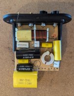
For interest, I attach a pic of the PCB with the two new Polys replacing the old Elecs (which were probably ok!); the 33uF had to be hot-glued off the end of the board!
I replaced the two Electrolytics (I thought it best to do the LF circuit's one too - if the HF one has gone, the other must be close!), and... no difference.
I have double-checked that it ain't the connecting terminals, nor the wires to the tweeters, nor the tweeters themselves; I removed both tweeters, and tried them in each cabinet in turn; both sound great in one cabinet, and around 1/4 volume in the other.
Checked for continuity as far as I could on the crossover PCB - from the input terminals to the first cap, all resistors and coils, etc, and all fine - but I cannot test the remaining caps by themselves. So, against all expectations, chances are that an original Poly cap is the culprit. So, I'll need to swap them to check :-(
For interest, I attach a pic of the PCB with the two new Polys replacing the old Elecs (which were probably ok!); the 33uF had to be hot-glued off the end of the board!
Attachments
- Home
- Loudspeakers
- Multi-Way
- Mission M66i Crossover faulty