Hi, i'm a hobbyst that remained stranded after my lab bench power supply died.
Here is what happened in details:
Power supply specifications:
220 - 240VAC input, 30V 10A MAX output.
Current and voltage can both be regulated from 0 to MAX. One day, i was using the power supply when it suddendly stopped working and its fuse was blown. (Fast 3.15A 250V).
So... Let's replace it and see if it works again. Plugged it in... Fuse blew again. So i opened the power supply to access the board, and found out that BOTH MOSFETs in the half bridge and the double diode were COMPLETELY shorted. Every pin to every pin.
So... Let's replace them, it will surely work again... And i replaced them with EVEN BETTER components (thats what i have for now). The mosfets were 500V 9A with 1+ ohm RDS(on).
I substituted them with 400V 24A 0.24 ohm RDS(on) mosfets. The double diode was 200v 20A and i substituted it with a whopping 60A 200V double diode (of course it is a shottky one).
This will also make the power supply slightly more efficent and heating will be reduced. New components and fuse set up.
Plugged it in, and it turned on! But... That was short lived. I tested it under load at 12V with a 12V 60W incandescent Light bulb. It worked. But after i rose the voltage a but more it broke again and the fuse blew.
Opened it up... EVERYTHING SHORTED AGAIN. Even the 60A double diode... Completely shorted. Frustrated, i changed the components again (same components as before) and then tested the power supply differently. I bypassed the fuse and i connected the power supply to a pure sine wave inverter with a soft start function and a series 100W incandescent light bulb to prevent catastrophic failure. The power supply turned on and i set the current to maximum and the voltage to 12V.
Then i started to short the output multiple times. Nothing bad happened. The voltage what set to 12V though. Then i set the voltage to 15V and after shorting / loading the output few times, it broke again and the light bulb went full brightness. This time thanks to the light bulb the two MOSFETs were saved, but one half of the double diode still shorted.
When the power supply was functional, i could short the output even with the voltage set to 30V and the current to maximum without any problems.
In 7 years NEVER a single problem. It always worked. So the question here is... WHERE LIES THE PROBLEM?
Does the main transformer have shorted turns? Some defective control IC? I tested all the rest of semiconductors in the board and they are not shorted / open circuit.
I would really appreciate it if you could help me resolve this problem. Without the power supply i cant do anything...
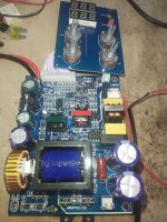
Here is a photo of the board in case you need it. I also measured the inductor and it seems fine (92uH).
The blue transformer is the main one, the green one is the gate driving transformer and the red one is used in a small secondary power supply to power the control electronics and display.
Here is what happened in details:
Power supply specifications:
220 - 240VAC input, 30V 10A MAX output.
Current and voltage can both be regulated from 0 to MAX. One day, i was using the power supply when it suddendly stopped working and its fuse was blown. (Fast 3.15A 250V).
So... Let's replace it and see if it works again. Plugged it in... Fuse blew again. So i opened the power supply to access the board, and found out that BOTH MOSFETs in the half bridge and the double diode were COMPLETELY shorted. Every pin to every pin.
So... Let's replace them, it will surely work again... And i replaced them with EVEN BETTER components (thats what i have for now). The mosfets were 500V 9A with 1+ ohm RDS(on).
I substituted them with 400V 24A 0.24 ohm RDS(on) mosfets. The double diode was 200v 20A and i substituted it with a whopping 60A 200V double diode (of course it is a shottky one).
This will also make the power supply slightly more efficent and heating will be reduced. New components and fuse set up.
Plugged it in, and it turned on! But... That was short lived. I tested it under load at 12V with a 12V 60W incandescent Light bulb. It worked. But after i rose the voltage a but more it broke again and the fuse blew.
Opened it up... EVERYTHING SHORTED AGAIN. Even the 60A double diode... Completely shorted. Frustrated, i changed the components again (same components as before) and then tested the power supply differently. I bypassed the fuse and i connected the power supply to a pure sine wave inverter with a soft start function and a series 100W incandescent light bulb to prevent catastrophic failure. The power supply turned on and i set the current to maximum and the voltage to 12V.
Then i started to short the output multiple times. Nothing bad happened. The voltage what set to 12V though. Then i set the voltage to 15V and after shorting / loading the output few times, it broke again and the light bulb went full brightness. This time thanks to the light bulb the two MOSFETs were saved, but one half of the double diode still shorted.
When the power supply was functional, i could short the output even with the voltage set to 30V and the current to maximum without any problems.
In 7 years NEVER a single problem. It always worked. So the question here is... WHERE LIES THE PROBLEM?
Does the main transformer have shorted turns? Some defective control IC? I tested all the rest of semiconductors in the board and they are not shorted / open circuit.
I would really appreciate it if you could help me resolve this problem. Without the power supply i cant do anything...
Here is a photo of the board in case you need it. I also measured the inductor and it seems fine (92uH).
The blue transformer is the main one, the green one is the gate driving transformer and the red one is used in a small secondary power supply to power the control electronics and display.
Attachments
Last edited by a moderator:

Post edited to make it readable 🙂 Please check you are not spacing everything out with multiple blank lines between each sentence.
Most SMPS failures are caused by failed electrolytic caps. Those small SMD aluminium electrolytics would/could be highly suspect as could any of the others. Checking the value is no good, they fail in other ways such as high E.S.R..
Sorry for the spacing.
I tested the ESR as well with an ESR meter and they seem fine. The small capacitors are less than 1 ohm.
Yes i used the power supply a lot in 7 years but not every day for hours...
So the capacitors are still good. Their lifetime is 5000 hours or more (at 105°C).
Maybe the transformer?
The FUUULL BRIDGE RECTIFAIAHH is good of course i checked it as well.
Without a circuit diagram this is wild guessing.
Is this smps a LLC converter? In that case overcurrent protection may be critical.
A shorted transformer winding should result in failure long before max load is reached.
Some years ago I analyzed a smaller chinese lab supply checking the circuit diagram -
what a crappy design, obviously copy/pasted circuit blocks merged together without any basic understanding.
What out of circuit tests have you done on all the caps to determine they are still good. The rated lifetime tells you nothing I'm afraid. 99% of SMPS failure is caused by failed electrolytic caps.So the capacitors are still good. Their lifetime is 5000 hours or more (at 105°C).
It is a normal half bridge with an output inductor. Not a resonant LLC. I checked it.
I know, those power supplies are not the best.
But thats what i could get then.
After all, it worked for 7 years...
I know, those power supplies are not the best.
But thats what i could get then.
After all, it worked for 7 years...
I checked them with an ESR meter. They all show very low impedance so they seem good. The ESR meter tests at 100kHz.What out of circuit tests have you done on all the caps to determine they are still good. The rated lifetime tells you nothing I'm afraid. 99% of SMPS failure is caused by failed electrolytic caps.
That problem seems to manifest when i raise the output voltage. The PSU uses TL494 for control.
I just dont know what else to do.
Maybe the transformer is actually shorted internally. Could it be?
I just dont know what else to do.
Maybe the transformer is actually shorted internally. Could it be?
I still would not be convinced 🙂 I've worked on countless SMPS over many years and cap failure is the most common issue. Also mundane things like dry joints and resistors gone high in value (usually high value resistors with high voltage across them). More rarely diode failure where they still work but run very hot and cause failure. Least common but it happens is failure of any very high voltage 'pulse caps' used for damping/tuning across the primary side of the switching transformer.
Any wound components would be way down the list of suspects.Maybe the transformer is actually shorted internally. Could it be?

I already checked Everything though... All resistors, semiconductors and capacitors are fine. The Red one is fine too (105J 400V polypropilene) measured at 1.004uF. Super precise.
Maybe some of the ICs broke. It could be that there was a strong voltage change in the power lines at that moment and it broke sensitive components too... Like some of the ICs.
Also another thing that i noticed is that if i short the output with thick wires or directly across the board contacts, i can hear high frequency noise from the power supply. But if i use a bit thinner wires that sound goes away. What!?
Maybe it just needs a little bit of series resistance?
Well that wont solve the problem though.
Its just to make it work better.
By the way this power supply wasnt very cheap after all. It cost me 76 euros.
Its value is less that that in my opinion though...
A decent PSU costs few hundreds / hundreds of euros...
Most often the failure occurs because of defective/intermittent defective electrolytic caps or diodes, less often ceramic caps (often the yellow or blue TH dipped disc type). The electrolytic caps look like types I would have replaced the day I received such a device 😉 Trouble with repair of SMPS is repeated catastrophic results when things are not yet 100%.
76 Euro is nothing and one can not expect much. Just the transformer for a linear PSU is more expensive. The switcher was simply EOL as most are after some time. Comes with the technology and price. Give in and have it recycled, repair will cost a multiple in time and parts.
76 Euro is nothing and one can not expect much. Just the transformer for a linear PSU is more expensive. The switcher was simply EOL as most are after some time. Comes with the technology and price. Give in and have it recycled, repair will cost a multiple in time and parts.
Last edited:
I will try to change all of the ICs and see if it works.
If it doesnt i will replace the SMD caps even though they look good but it probably wont make any difference...
If it still does not work the last thing remaining is the transformer. Maybe it overheated and it developed shorted turns.
Because sometimes i used the power supply at maximum power for few hours, to charge a big battery.
The day it first broke i was using it at almost maximum power. It was powering peltier modules and a powerful fan at 24V / 9.5+ amps. So it might be possible that the transformer gave up.
Its difficult to advise further. If you are 100% sure that:
then there isn't much else left 🙂
You must be very sure also that the parts you have replaced are all suitable. There are a lot of unknowns at this point.
But you say you have measured and tested the caps! The small SMD can type electrolytics are all highly suspect
I already checked Everything though... All resistors, semiconductors and capacitors are fine.
then there isn't much else left 🙂
You must be very sure also that the parts you have replaced are all suitable. There are a lot of unknowns at this point.
If it doesnt i will replace the SMD caps even though they look good
But you say you have measured and tested the caps! The small SMD can type electrolytics are all highly suspect
I dont know, maybe when under stress their performance worsens. They might be 'intermittent'. I saw that this behaviour on some capacitors can actually happen.
It measures good, but when under stress its performance goes down significantly.
I know what all the ICs are. So its easy to replace them. No sandpapered ICs in this power supply, fortunately. All the markings are readable.
Well, i'll try my best and see what i can do...
It measures good, but when under stress its performance goes down significantly.
I know what all the ICs are. So its easy to replace them. No sandpapered ICs in this power supply, fortunately. All the markings are readable.
Well, i'll try my best and see what i can do...
You mention an inductor and an 1uF polypropylen cap.
That smells like LLC for me.
You replaced transistors by bigger ones.
This is not always a good idea, as it affects critical dead times.
What we know that things blow if you go to the power limit of your device.
Which may be well related to primary circulating currents crossing a critical boundary.
Personally I decided to avoid any al cheapo switchmode lab supplies,
they are crap, period. Ditch it and go for a used linear lab supply.
Or buy from a reputable supplier. like GWInstek, Rigol etc
Last edited:
After a while one sees similarities between cheap chinese electrolytic caps and chinese fire crackers.
Anyway, if one replaces electrolytic caps with unpronouncable brand names and non existing datasheets for known good quality caps at least those are ruled out from premature EOL.
Anyway, if one replaces electrolytic caps with unpronouncable brand names and non existing datasheets for known good quality caps at least those are ruled out from premature EOL.
No, that capacitor is just in series with the primary of the transformer. The inductor is on the secondary side.
As an option, the choke on the yellow ring after the transformer can fool your head like that. Such a core on sprayed iron has a service life and loses its permeability when heated.
The exact value of inductance that should be can be found out using a calculator from the manufacturer, knowing the number of turns and the brand of the core material and its size, the brand of the core is -26. But there is another problem, when this material wears out, it begins to heat up a lot, you just need to turn on the power supply and monitor the temperature of this core, if it is higher than 65 degrees Celsius, then perhaps it is time to change it. When the core heats up, its magnetic permeability decreases and as a result, the inductance of the choke decreases.But it measures as 92uH... Should it be higher?
- Home
- Amplifiers
- Power Supplies
- UNFIXABLE power supply!!?