Hi,
I am not sure this is the best place to ask for your help with a couple of questions. So, please let me know if I should post this in a different sub forum.
it is about how ground is managed in Japan, because I have a SET amplifier from Japan.
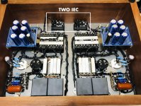
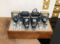
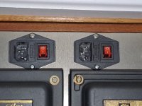
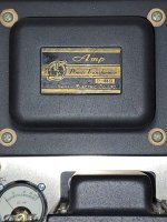
I bought a 100V DIY Japanese dual mono SET amplifier that has a couple of 717As per channel driving either a 300B, 2A3, or a 45. The amplifier has fixed bias, hum pots, and a knob to select the operating point for either a 300B, 2A3 or 45 tube. The amplifier has two IECs in the back, one for each channel and each IEC has 3 prongs.
You can see all that in the pictures attached. Unfortunately, I do not have the schematics of the amplifier.
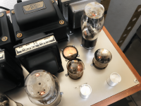
I am going to use the amplifier in the United States. Surely, the amplifier, being made in Japan, works with 100V and either 50hz or 60hz. The power transformers are Sansui P- 44B which I believe can work either with 50hz or 60hz. So, HZ should not be an issue.
These are my questions:
1. For the voltage and ground issue, I am planning to use this step down transformer, which has 2 outlets for 100V, in 1600 Watts, which should be more than enough even with the 300Bs in place. But, I am a bit confused with the ground issue. Clearly the IECs in the amplifier have 3 prongs, and the IEC outlet in the step down transformer linked above, has also 3 prongs. So, I was planning to simply use a common USA power cord from the IEC in the amplifier to the step down transformer outlet, is that OK to safely handle the ground or am I missing something? I am not sure how the ground is handle in the amplifier, but maybe someone can understand that by looking at one of the pictures attached that shows the wiring.
2. The amplifier also has 2 hum pots. Regarding the hum pots, I was planning to do what I usually do which is: Let the amp warm up for at least 30 sec without music, turn the hum pots clockwise until I hear the hum increase. Then turn counter-clockwise until the hum decreases and then increases again to about the level
where I stopped the clockwise rotation. And then, set the pot to the middle of these two positions. Is that OK or am I missing something?
Any help is greatly welcome.
Thanks in advance!
Alan
I am not sure this is the best place to ask for your help with a couple of questions. So, please let me know if I should post this in a different sub forum.
it is about how ground is managed in Japan, because I have a SET amplifier from Japan.
I bought a 100V DIY Japanese dual mono SET amplifier that has a couple of 717As per channel driving either a 300B, 2A3, or a 45. The amplifier has fixed bias, hum pots, and a knob to select the operating point for either a 300B, 2A3 or 45 tube. The amplifier has two IECs in the back, one for each channel and each IEC has 3 prongs.
You can see all that in the pictures attached. Unfortunately, I do not have the schematics of the amplifier.
I am going to use the amplifier in the United States. Surely, the amplifier, being made in Japan, works with 100V and either 50hz or 60hz. The power transformers are Sansui P- 44B which I believe can work either with 50hz or 60hz. So, HZ should not be an issue.
These are my questions:
1. For the voltage and ground issue, I am planning to use this step down transformer, which has 2 outlets for 100V, in 1600 Watts, which should be more than enough even with the 300Bs in place. But, I am a bit confused with the ground issue. Clearly the IECs in the amplifier have 3 prongs, and the IEC outlet in the step down transformer linked above, has also 3 prongs. So, I was planning to simply use a common USA power cord from the IEC in the amplifier to the step down transformer outlet, is that OK to safely handle the ground or am I missing something? I am not sure how the ground is handle in the amplifier, but maybe someone can understand that by looking at one of the pictures attached that shows the wiring.
2. The amplifier also has 2 hum pots. Regarding the hum pots, I was planning to do what I usually do which is: Let the amp warm up for at least 30 sec without music, turn the hum pots clockwise until I hear the hum increase. Then turn counter-clockwise until the hum decreases and then increases again to about the level
where I stopped the clockwise rotation. And then, set the pot to the middle of these two positions. Is that OK or am I missing something?
Any help is greatly welcome.
Thanks in advance!
Alan
Attachments
-
 Japanese Dual Mono SET- 717A to 2A3-45-300B - 1 copy.jpg549.4 KB · Views: 199
 -
 Japanese Dual Mono SET- 717A to 2A3-45-300B - 7.png1.2 MB · Views: 178
 -
 Japanese Dual Mono SET- 717A to 2A3-45-300B - 3.png1.2 MB · Views: 159
 -
 WhatsApp Image 2024-07-26 at 10.05.54.jpeg515.9 KB · Views: 156
 -
 WhatsApp Image 2024-07-26 at 10.06.08.jpeg363.9 KB · Views: 170
Last edited:
Bump, perhaps someone more knowledgeable than me can help.
Some of the old Sansui were designed for both domestic and overseas having different taps on the primary and a hefty EI core. The AU-111 was like that; I gather that it was popular with US Servicemen stationed in Japan. I recall Rod Elliots website has some useful electrical safety wiring articles that might be relevant.
Some of the old Sansui were designed for both domestic and overseas having different taps on the primary and a hefty EI core. The AU-111 was like that; I gather that it was popular with US Servicemen stationed in Japan. I recall Rod Elliots website has some useful electrical safety wiring articles that might be relevant.

Our 60Hz AC line is fine. Use standard IEC power cords.
Are you certain this amplifier was actually used in Japan, and not built for use in the USA?
Hum adjustment is correct. If there is a plate current bias adjustment, make that first.
Since this is a DIY amplifier, strongly urge you to locate a schematic for future repairs.
Are you certain this amplifier was actually used in Japan, and not built for use in the USA?
Hum adjustment is correct. If there is a plate current bias adjustment, make that first.
Since this is a DIY amplifier, strongly urge you to locate a schematic for future repairs.
That will work rewired to 110V without the step down transformer. That is good news as superfluous stuff is superfluous.
Both transformers need only the wire connected to the 100V connection to be connected to the 110V connection which is the fourth position.
Both transformers need only the wire connected to the 100V connection to be connected to the 110V connection which is the fourth position.
Attachments

Well, a 3-prong power cord from the amp to the transformer sounds right to me, if both are set up for it. Why not?
My house here in Japan has 2-prong wall outlets. A couple of those in the kitchen and the one next to the bathroom, for the washing machine, are additionally provided with a grounding post, for attaching a ground wire. All others have no provision for grounding.
Most electrical devices are supplied with a 2-prong cord, PCs with 3-prong (possibly monitors as well, but I don't remember). 2-prong power cords sometimes but not always have a pigtail ground wire, power strips are a mish-mash of 2-prong sockets or 3-prong sockets and with or without ground wire, though the wire is unusable if, as I have to, the strip will be plugged into an ungrounded and ungroundable outlet.
All an irritation and once a source of concern, coming as I do from a country where it has always been 3-prong plugs to 3-prong sockets, which keeps things nice and simple. But I gave up worrying about grounding years ago, and now I just use an RCD (GFCI) plug into the power strip or the wall when using devices where I think it would be good to have the protection. In any case, all circuits in the house are connected to GFCI breakers at the distribution board.
See image above that I found for the Sansui P44-B. Nameplate suggests the transformer's primary can be reconfigured for 110VAC, which should be fine for use in the USA. It should be necessary to move only one connection to the transformer, from the 100V tap to the 110V tap. This might give better results (and certainly less expensive) than trying to use an outboard step-down transformer.
The device appears to have the PE connection of the IEC inlet wired to the chassis just as it should be for correct and international agreed safety regulations albeit in a non standard color code. In fact all wiring is black which is uncommon (just like 2 IEC inlets!).
A test with DMM could prove if things are like seen. Certainly with high(er) voltage stuff things should be safe to the touch.
A test with DMM could prove if things are like seen. Certainly with high(er) voltage stuff things should be safe to the touch.
Thanks all for your help!
I am sure the amplifier was made for Japan since I bought it in Yahoo Auctions Japan through a Japanese company that works as an agent between buyer and seller. Mainly, because to bid in Yahoo Auctions Japan you need to have a Japan based bank account or credit card, and/or a Japan phone number. So, it is almost impossible to bid in Yahoo Auctions Japan without an agent.
Unfortunately, it would be very hard to get an schematic but I will try to contact the seller and see if I can get one.
The power transformer has a 110V tap indeed as the picture shows above, but if I use that tap I would need to recheck the operating points of all the tubes. And, so, to avoid that, I may prefer to leave the transformer on the 100V tap, and I will use a Variac that has two outlets, for the two power cords, the Variac can put out 100v to each outlet and I can easily verify that with a Kill A Watt meter.
I am dealing with two things now, ground and polarity.
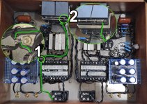
One is to verify if the ground is properly connected inside the amplifier. If you look at the complete photo of the amplifier, below. That shows in green the ground path coming out from the fused IEC power switch. I know that prong is ground because I found a wiring diagram for that power switch online. In that photo you can see that the green line carrying ground meets another two lines in a first stop (Number 1 in the picture) and gets attached to the plate of the amp, and then it goes to stop 2. (Number 2 in the photo). So, i think that ground is OK in the amplifier, right?

The second one is to make sure that the polarity inside the amplifier and in the fused power switch, picture below, is correctly. The amplifier has two of those.

Below is the correct wiring for the fused power switch for USA polarity.

And below, is the crazy way this switch is wired in my amplifier.

I am trying to get my head around this wiring.
If I understand correctly, AC is alternating current so polarity only matters in terms of cutting/stopping/opening the live wire connection when a power switch is in the OFF position. That way, when the power switch is in the OFF, there is no live current passing through the device, right?
Then, after AC goes through the power switch and into the amplifier, polarity does not matter since the power transformer does not see polarity, is that correct?
Taking into account that it is the live/hot wire that should always be fused, then I guess that the yellow cable is live/hot?
But, then why the cable in yellow is connected to the fused live/hot? sort of bypassing the power switch?
I am sure the amplifier was made for Japan since I bought it in Yahoo Auctions Japan through a Japanese company that works as an agent between buyer and seller. Mainly, because to bid in Yahoo Auctions Japan you need to have a Japan based bank account or credit card, and/or a Japan phone number. So, it is almost impossible to bid in Yahoo Auctions Japan without an agent.
Unfortunately, it would be very hard to get an schematic but I will try to contact the seller and see if I can get one.
The power transformer has a 110V tap indeed as the picture shows above, but if I use that tap I would need to recheck the operating points of all the tubes. And, so, to avoid that, I may prefer to leave the transformer on the 100V tap, and I will use a Variac that has two outlets, for the two power cords, the Variac can put out 100v to each outlet and I can easily verify that with a Kill A Watt meter.
I am dealing with two things now, ground and polarity.
One is to verify if the ground is properly connected inside the amplifier. If you look at the complete photo of the amplifier, below. That shows in green the ground path coming out from the fused IEC power switch. I know that prong is ground because I found a wiring diagram for that power switch online. In that photo you can see that the green line carrying ground meets another two lines in a first stop (Number 1 in the picture) and gets attached to the plate of the amp, and then it goes to stop 2. (Number 2 in the photo). So, i think that ground is OK in the amplifier, right?
The second one is to make sure that the polarity inside the amplifier and in the fused power switch, picture below, is correctly. The amplifier has two of those.
Below is the correct wiring for the fused power switch for USA polarity.
And below, is the crazy way this switch is wired in my amplifier.
I am trying to get my head around this wiring.
If I understand correctly, AC is alternating current so polarity only matters in terms of cutting/stopping/opening the live wire connection when a power switch is in the OFF position. That way, when the power switch is in the OFF, there is no live current passing through the device, right?
Then, after AC goes through the power switch and into the amplifier, polarity does not matter since the power transformer does not see polarity, is that correct?
Taking into account that it is the live/hot wire that should always be fused, then I guess that the yellow cable is live/hot?
But, then why the cable in yellow is connected to the fused live/hot? sort of bypassing the power switch?
Attachments

Last edited:
Setting the voltage to the right windings is the only way to do things right and rechecking of operating points is a necessity anyway after transport. Shortest path from A to B. Diesel in Diesel cars, 110V to 110V taps etc. Anything extra needed in-between without real reason is a sign of incompetence/useritis.
Just check if chassis is connected to the PE pins and please use the right terms. Ground and PE are not the same. If that is not known don't bother. Focus on doing things the right way. Also measure operating points and filament voltages as it could very well be that mains tolerances are calculated in. For instance 110V +10/-6% as mains voltages go up everywhere because of solar and wind energy. If the filament voltages are OK then all is good.
The power switch should be DPDT in 2024 and switching both L and N for 100% electrical safety. It appears this manufacturer does not know this yet. Tube world, emotion is quality, ears are instruments and safety is only a detail. Also Audio GND and PE seem interconnected (sometimes chassis is only connected to Audio GND and PE is floating, weird). Certainly when importing devices correction is often needed so work to correct a newly bought device. Only to be done when one knows what to do and also knows how to work safely when working with high DC voltages.
Last edited:
@jean-paul
Power at my wall here in north Virginia is 121 to 123 volts, not 110V. So, even if I change the power transformer tap to 110v, I would need a bucking transformer to get down from 122 volts to 110 volts.
What do you mean by chase? Maybe, you meant to say chassis?
What are the protective earth pins? where are they located?
It appears this manufacturer does not know this yet.
The device was described as a DIY amp. The manufacturer of the power switch is not visible in the photos, I think. If Japanese, it will be compliant with regulations in the market(s) for which it was intended. However, if the amp is fully DIY rather than kit-built, there's no saying which country the switch and other parts are from. Switches and power cords from Chinese manufacturers are easily available in Japan and generally cheaper.
The use of a variac and measuring will tell. Possibly things are not as they seem. Example: many chinese manufacturers produce transformers for 230V countries but have 220V written on the products. Quite a lot of people here still say “two-twenty” even after 30 years of 230. One also sees new products with 220V written on them which is rather silly. The USA has 120V by now but one still sees 110V or 115V taps in relatively recent products meant for the USA.
A power transformers primaries tolerates mains voltage variations till a certain maximum. Here we measure between 240 and 250 while officially having 230V. It is within the +10/-6% tolerance. +10% is no problem, it are the secondary voltages that count in devices with unregulated filament power supplies.
So it depends on the age, the design parameters of that Sansui transformer and what it measures with load when connected to 120V.
Last edited:
The ones you marked "ground", which seems fairly standard usage in the US, along with "safety ground" etc. when drawing a distinction with signal ground. I think people often omit the distinction when they assume it's going to be inferred.What are the protective earth pins? where are they located?
"Earth" is preferred in some countries, such as most of the English-speaking countries outside North America, and I expect it's widely used in Europe.
Sorry if I'm mentioning what you already know. Maybe your question went over my head. Things do. But the pins on the IEC inlets are marked with "E": that's your earth pin, which Jean-Paul was saying needs to be wired to the chassis.
Side note for anyone who knows more about this than me: Japan uses TT earthing, which may explain the prevalence of two-prong outlets in the residential setting (along with the GFCI breakers): every apartment and house I've lived in has been that way. Would this account for oddities with the IEC wiring in the amp?
Not directly related (or perhaps it is) but I'm mildly interested in what motivated Inkasound to buy a DIY amp from the other side of the world: it does seem to result in some additional issues, make it difficult and expensive to return if needed, and present potential challenges that not everyone (e.g. me) would be keen to face.
Having two IEC sockets smells like dumb DIY to me and makes me very cautious of everything else down stream:
- I don't see any bleed resistors!
- Creating two HT supplies from different taps of the same winding. One solid state, the other tube rectifier with a 150mA choke.
- Four 717A seems like a very poor choice. Their 2x150mA heater might not be sufficient load to pull the voltage down to 6.3v on the 3a winding. Their HT max current and voltage are too low to adequatly drive those output tubes. In Triode, Mu is only around 20. They're also expensive and rare. Wonder how they're configured.
- Wonder what fuse rating they put in the IEC sockets.
- If it was mine I'd hand draw the circuit from what can be seen and post it here.
Looks indeed like someone that had a schematic for a single channel just build 2 of them in the same chassis without knowing enough to even do the most basic cleanup.Having two IEC sockets smells like dumb DIY to me and makes me very cautious of everything else down stream:
Very sensible suggestion. If it isn't useful now, it can be in future.If it was mine I'd hand draw the circuit from what can be seen and post it here.
Looks like that amp was wired up in a weird way. Does it have an UL label or equivalent? If not, it may not be legal to plug it in due to safety regulations.
- Home
- Amplifiers
- Tubes / Valves
- Using a Japanese SET amplifier in the USA (Ground , Voltage, and Hz)