Hey all,
Does anyone have a schematic for a US amps AX3200DE amplifier? I’m trying to work out why it’s not oscillating but I’m coming up short.
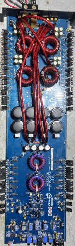
This amp came to me already worked on and it was in a mess. Ive replaced the power supply section (fets, gate resistors, driver transistors) and the output section (fets, all drive transistors) and I can’t get any oscillation at all to take place.
I’ve attached the schematic that I’m using as it is similar, but it’s missing some stuff in the output section. I’ve got all my 12V voltages, negative and positive rails, and I’ve got PWM coming into the output section but it stops right at “Q44” on the diagram that I have. “Q43” I have my PWM but it don’t go any further. Even when I inject a signal it don’t go anywhere.
I’ve replaced random diodes, resistors, and even the TL072 that feeds the PWM to the rest of the output section. What am I missing?
Does anyone have a schematic for a US amps AX3200DE amplifier? I’m trying to work out why it’s not oscillating but I’m coming up short.
This amp came to me already worked on and it was in a mess. Ive replaced the power supply section (fets, gate resistors, driver transistors) and the output section (fets, all drive transistors) and I can’t get any oscillation at all to take place.
I’ve attached the schematic that I’m using as it is similar, but it’s missing some stuff in the output section. I’ve got all my 12V voltages, negative and positive rails, and I’ve got PWM coming into the output section but it stops right at “Q44” on the diagram that I have. “Q43” I have my PWM but it don’t go any further. Even when I inject a signal it don’t go anywhere.
I’ve replaced random diodes, resistors, and even the TL072 that feeds the PWM to the rest of the output section. What am I missing?
Attachments
-1.84V across both those resistors.
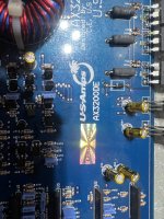
Here’s where the circuit isn’t doing the same thing as the diagram. There’s a couple extra transistors feeding Q43 and Q44. They are feeding 49.95V to the collectors of Q43 and Q44. Rail voltage sits at around -/+100V coming from the rectifiers.
Here’s where the circuit isn’t doing the same thing as the diagram. There’s a couple extra transistors feeding Q43 and Q44. They are feeding 49.95V to the collectors of Q43 and Q44. Rail voltage sits at around -/+100V coming from the rectifiers.
Attachments

The protect led is not lit.
Black meter probe on emitter pin 1, DCV @ pin 2 collector is 11.97V, DVC @ base pin 3 is 0.135V
Black meter probe on emitter pin 1, DCV @ pin 2 collector is 11.97V, DVC @ base pin 3 is 0.135V
I did check R59 already as I was going down through this road too. R59 was OK at the time and C44 was OK as well. I even temporarily replaced C44 as I was suspecting some stuff with it.
R59 is 0.570V on the side connected to the diode pair D19 anode, and the other side is 12.46V.
R59 is 0.570V on the side connected to the diode pair D19 anode, and the other side is 12.46V.
Lift/remove R2. Does the amp power up?
If not, remove Q2. Does that help.
If the amp is not in protect, these should be safe but be careful when powering up.
If not, remove Q2. Does that help.
If the amp is not in protect, these should be safe but be careful when powering up.
I removed R2 first and the amp still powers up, no change/oscillation in the output section. I removed Q2, same thing. I checked Q2 and it checks OK.
Oddly enough, with Q2 removed, its collector pin (2) starts off at 1-2V and gradually increases to 12.1V. Maybe that’s a consequence of Q2 being removed?
No it does not.
Octocoupler pin 1 - 12.45V, pin 2 - 11.73V, pin 3 - 0V, and pin 4 - 53.80V. (Meter black probe to ground)
I’m assuming when the octocoupler turns on then it’s going to put the amp in mute? It’s going to dump the 53.80V to ground?
Octocoupler pin 1 - 12.45V, pin 2 - 11.73V, pin 3 - 0V, and pin 4 - 53.80V. (Meter black probe to ground)
I’m assuming when the octocoupler turns on then it’s going to put the amp in mute? It’s going to dump the 53.80V to ground?
Ok so. This is why I’d love a schematic for one of these. So confusing.
I ended up removing R63 thinking it was R2
I checked R63 and yes it’s 985ohms which is within spec.
I reinstalled R63, removed R2 and powered the amp up.
Optocoupler pin 1 - slowly builds to 7.49V, pin 2 - 6.33V, pin 3 - 0V, pin 4 - 0.98V. Black meter probe on ground.
I ended up removing R63 thinking it was R2
I checked R63 and yes it’s 985ohms which is within spec.
I reinstalled R63, removed R2 and powered the amp up.
Optocoupler pin 1 - slowly builds to 7.49V, pin 2 - 6.33V, pin 3 - 0V, pin 4 - 0.98V. Black meter probe on ground.
- Home
- General Interest
- Car Audio
- US Amps AX3200DE Schematic