Thanks to Schmitz77 for sparking my interest on the subject,
I am still fascinated by unusual tube circuit (read Shindo) I started collecting various tube configuration of EF86, EF80 circuit.
The first circuit comes from this thread posted by Schmitz77 :
https://www.diyaudio.com/community/threads/cathodyne-tube-line-pre.355172/
I went a little further and made a ltspice sketch and sim

FYI this is only the line stage, I'll concentrate on the phono stage later.
The most valuable info came from Stereophile, as Mr Dudley wrote :
- "The C3m is also capable of very high gain, but Ken Shindo puts it to a different sort of use: In the Vosne-Romanee, the Siemens tube functions as a resistance-coupled phase inverter, the output of which appears across the anode and the cathode."
- "The now-balanced signals for the left and right channels are directed to that pair of vintage output transformers, with DC blocking along the way by those large, lovely, and similarly ancient Sprague oil caps."
- "We brought up the volume just to the point of clipping and noted an output of approximately 5.5V RMS (which translates to just under 8V peak, possibly explaining the output level spec provided for the V-R on the Shindo site)"
From a theoretical standpoint, the split phase phase inverter comes from this reference (chap 10, page 217)

Anyways, I'm thinking building this project in the future and I wanted to know if anyone can give me some pointers on what to look for next,
I did a simulation on the frequency response, and I don't think it looks right,
Have fun fellow DIYers!
Oli
(I can link the EF80 and C3m Ltspice data I used for my schematic)
I am still fascinated by unusual tube circuit (read Shindo) I started collecting various tube configuration of EF86, EF80 circuit.
The first circuit comes from this thread posted by Schmitz77 :
https://www.diyaudio.com/community/threads/cathodyne-tube-line-pre.355172/
I went a little further and made a ltspice sketch and sim
FYI this is only the line stage, I'll concentrate on the phono stage later.
The most valuable info came from Stereophile, as Mr Dudley wrote :
- "The C3m is also capable of very high gain, but Ken Shindo puts it to a different sort of use: In the Vosne-Romanee, the Siemens tube functions as a resistance-coupled phase inverter, the output of which appears across the anode and the cathode."
- "The now-balanced signals for the left and right channels are directed to that pair of vintage output transformers, with DC blocking along the way by those large, lovely, and similarly ancient Sprague oil caps."
- "We brought up the volume just to the point of clipping and noted an output of approximately 5.5V RMS (which translates to just under 8V peak, possibly explaining the output level spec provided for the V-R on the Shindo site)"
From a theoretical standpoint, the split phase phase inverter comes from this reference (chap 10, page 217)
Anyways, I'm thinking building this project in the future and I wanted to know if anyone can give me some pointers on what to look for next,
I did a simulation on the frequency response, and I don't think it looks right,
Have fun fellow DIYers!
Oli
(I can link the EF80 and C3m Ltspice data I used for my schematic)
Attachments
Try this one. It was generated by Derk Reefman using uTracer. URL: ExtractModel by Derk ReefmanCan you post the EF80 spice model???? I don't have it.
Code:
****************************************************
.SUBCKT EF80 1 2 3 4 ; A G2 G1 C;
* ExtractModel V .997
* Model created: 07-Dec-13
X1 1 2 3 4 PenthodeDE  MU= 54.7 EX=1.202 kG1= 136.4 KP= 340.3 kVB =  4670.0 kG2=  584.2
+ Ookg1mOokG2=.56E-02 Aokg1=.23E-05 alkg1palskg2=.56E-02 be=  .054 als=  3.09 RGI=2000
+ CCG1=7.5P CCG2=5.4P  CPG1 = 0.007p CG1G2 = 2.6p CCP=0.012P  ;
.ENDS
****************************************************
.SUBCKT PenthodeDE 1 2 3 4; A G2 G1 C
RE1  7 0  1MEG    ; DUMMY SO NODE 7 HAS 2 CONNECTIONS
E1 7 0 VALUE=
+{V(2,4)/KP*LOG(1+EXP(KP*(1/MU+V(3,4)/SQRT(KVB+V(2,4)*V(2,4)))))}
E2   8 0 VALUE = {Ookg1mOokG2 + Aokg1*V(1,4) - alkg1palskg2*Exp(-be*V(1,4)*SQRT(be*V(1,4)))}
G1   1 4  VALUE = {0.5*(PWR(V(7),EX)+PWRS(V(7),EX))*V(8)}
G2   2 4 VALUE = {0.5*(PWR(V(7),EX)+PWRS(V(7),EX))/KG2 *(1+als*Exp(-be*V(1,4) * SQRT(be*V(1,4))))}
RCP  1 4  1G      ; FOR CONVERGENCE    A  - C
C1   3 4  {CCG1}   ; CATHODE-GRID 1    C  - G1
C4   2 4  {CCG2}   ; CATHODE-GRID 2    C  - G2
C5   2 3  {CG1G2}   ; Grid 1-GRID 2    G1  - G2
C2   1 3  {CPG1}  ; GRID 1-PLATE    G1 - A
C3   1 4  {CCP}   ; CATHODE-PLATE    A  - C
R1   3 5  {RGI}   ; FOR GRID CURRENT    G1 - 5
D3   5 4  DX      ; FOR GRID CURRENT    5  - C
.MODEL DX D(IS=1N RS=1 CJO=10PF TT=1N)
.ENDS PenthodeDE
Thanks to Schmitz77 for sparking my interest on the subject,
I am still fascinated by unusual tube circuit (read Shindo) I started collecting various tube configuration of EF86, EF80 circuit.
The first circuit comes from this thread posted by Schmitz77 :
https://www.diyaudio.com/community/threads/cathodyne-tube-line-pre.355172/
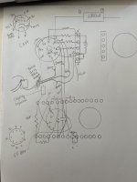
I went a little further and made a ltspice sketch and sim
View attachment 1331333
FYI this is only the line stage, I'll concentrate on the phono stage later.
The most valuable info came from Stereophile, as Mr Dudley wrote :
- "The C3m is also capable of very high gain, but Ken Shindo puts it to a different sort of use: In the Vosne-Romanee, the Siemens tube functions as a resistance-coupled phase inverter, the output of which appears across the anode and the cathode."
- "The now-balanced signals for the left and right channels are directed to that pair of vintage output transformers, with DC blocking along the way by those large, lovely, and similarly ancient Sprague oil caps."
- "We brought up the volume just to the point of clipping and noted an output of approximately 5.5V RMS (which translates to just under 8V peak, possibly explaining the output level spec provided for the V-R on the Shindo site)"
From a theoretical standpoint, the split phase phase inverter comes from this reference (chap 10, page 217)
View attachment 1331336
Anyways, I'm thinking building this project in the future and I wanted to know if anyone can give me some pointers on what to look for next,
I did a simulation on the frequency response, and I don't think it looks right,
Have fun fellow DIYers!
Oli
(I can link the EF80 and C3m Ltspice data I used for my schematic)
Very interesting post @zonula! Your LTspice circuit looks very good. You might like to look through my thread Tube Bias its all about triodes.
What's the purpose of R10, don't think you need it 👍
C3 takes away local negative feedback from U1, the THD will be better without it. Plot the output of U1 at its Anode and then do a FFT, it will show you THD.
-
Last edited:

The secondary, from your Output-Transformer, ist grounded. Thats why you have no symmetrical Signal.
Regards
Dieter
Regards
Dieter
Compare the schematic in post #9 and yours.Why is one of the phase of my output skewed?
- Home
- Amplifiers
- Tubes / Valves
- Cathodyne tube line pre (cont'd)