then I came across this one https://www.ebay.com/itm/3335899805...HkYeLfncaHSDpt2ccXKdOU/w==|tkp:Bk9SR-Cz5-CRZA
Is
Can it be used with
Is
TDA1387
a good dac?Can it be used with
SAA7220?
Both verisions?
Yes you can use TDA1387 with SAA7220. Its nowhere near as good a DAC as TDA1541A - primarily its noise specs are considerably poorer, its distortion also isn't as good. If you parallel very many of them you can improve the noise a lot but the distortion won't get much better.
I got a hold of a TDA1541A.Yes you can use TDA1387 with SAA7220. Its nowhere near as good a DAC as TDA1541A
Hi,Yes you can use TDA1387 with SAA7220. Its nowhere near as good a DAC as TDA1541A - primarily its noise specs are considerably poorer, its distortion also isn't as good. If you parallel very many of them you can improve the noise a lot but the distortion won't get much better.
What is your opinion about the ProtoDac that uses 8 x tda1387 in parallel?
What could be improved? Would an external clock bring any real benefit?
Tks
Nilton
I've not listened to the ProtoDac so can only speculate based on its similarity to some of my earlier designs. What could be improved would be a low-noise PSU to the DAC chips - though I understand that's not on the board. Also feeding the current output via a passive filter before I/V helps to clean up the high freqs quite a lot. I haven't any experience with improving clocks so don't know about that. I would guess though that it isn't the low-hanging fruit here - PSU and filtering would be the things to address. Oh and its possible to increase the output current by upto 50% with a suitable resistor from VDD to pin7, this may well lower the noise.
Hi Benson, I am looking for 1 or 2 TDA1541 DAC chips for Gabster TD1 DAC board.I still have some TDA1541A’s for sale.
@abraxalito Tks for the tips!
Could the passive filter be an inductor in series with the +5V on pin 28?
As for the resistor to increase current, would it go from the same pin 28 to pin 7, which is not normally used? (sorry for my stupid drawing...):

Also, I read something about Dark Red, is it just the filter before the I/V, or is it the I/V stage with the filter included in the circuit?
Tks!
Could the passive filter be an inductor in series with the +5V on pin 28?
As for the resistor to increase current, would it go from the same pin 28 to pin 7, which is not normally used? (sorry for my stupid drawing...):
Also, I read something about Dark Red, is it just the filter before the I/V, or is it the I/V stage with the filter included in the circuit?
Tks!
Attachments

That would be a power supply filter rather than a signal filter. It certainly can reduce PSU noise but the inductor needs to have a low DC impedance and hence will be a bit bulky. The DAC module itself draws a signal dependent current which will result in modulation of the supply - this can be reduced significantly though by running the module in balanced mode. Meaning sending L & -L to it rather than L & R. Of course you'll need a second module to handle the R channel and an I2S splitter to generate the balanced digital signals.Could the passive filter be an inductor in series with the +5V on pin 28?
As for the resistor to increase current, would it go from the same pin 28 to pin 7, which is not normally used? (sorry for my stupid drawing...):
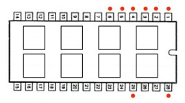
Does the module connect all pin7s together? If it does then yes, a resistor from pin28 to pin7 would do the trick. If not, then individual resistors. I've used around 110k individually.
Also, I read something about Dark Red, is it just the filter before the I/V, or is it the I/V stage with the filter included in the circuit?
The Dark LED has an I/V stage plus an LC filter - it can be used with TDA1387s (I've done it) but really it deserves a lower noise DAC chip. The TDA1387*8 module has too much output current for Dark LED, you'd really only want TDA1387*4 to suit it. I suppose you could fit a resistor from pin7 to GND to reduce the output current.
Hi, sorry, all are gone.Hi Benson, I am looking for 1 or 2 TDA1541 DAC chips for Gabster TD1 DAC board.
That would be a power supply filter rather than a signal filter. It certainly can reduce PSU noise but the inductor needs to have a low DC impedance and hence will be a bit bulky. The DAC module itself draws a signal dependent current which will result in modulation of the supply - this can be reduced significantly though by running the module in balanced mode. Meaning sending L & -L to it rather than L & R. Of course you'll need a second module to handle the R channel and an I2S splitter to generate the balanced digital signals.
In your opinion, what would be better:
1) assemble two dacs with independent power supplies and transformers (in this case, could I use a 4:1 step-down transformer to convert the 2 outputs of each Dac into an unbalanced output, in something like the image below?), or:
2 ) mount two modules on a single board, with only one power supply, which would save two I/V resistors and 2 decoupling capacitors? (in this case, how are the L & R outputs of each module converted into L & -L, and R & -R?)
I will only realize it when I get the modules in hands... But I would bet that only used pins are paralleled...Does the module connect all pin7s together? If it does then yes, a resistor from pin28 to pin7 would do the trick. If not, then individual resistors. I've used around 110k individually.
Thanks for your time and teachings

I would definitely recommend your option 2), can't see any advantage from option 1). The L/R outputs are created by an I2S splitter, I have such a design using a small board of HC logic (shift regs, muxes). To run balanced you'd not save any I/V resistors, rather you'll need twice as many as unbalanced as you'll have four channels : L+,L-,R+,R-.
Did you creat this design for commercial purposes? Do you have boards to sell?The L/R outputs are created by an I2S splitter, I have such a design using a small board of HC logic (shift regs, muxes).
After running the modules in balanced mode in the digital domain, could the analog outputs become unbalanced if the next step have no balanced inputs? Would this affect the noise?
Tks
Yes to both your questions. If you're interested, drop me a PM.
If the next stage in the signal chain doesn't accept a balanced input then you will lose most of the advantages of going balanced. Not all the advantages though as the stability of the DAC power rail remains even when an unbalanced output is taken. You will lose the signal-to-noise advantage if your next stage doesn't have a balanced input. I often use a transformer between DAC and amp, that's one way to take advantage of balanced outputs.
If the next stage in the signal chain doesn't accept a balanced input then you will lose most of the advantages of going balanced. Not all the advantages though as the stability of the DAC power rail remains even when an unbalanced output is taken. You will lose the signal-to-noise advantage if your next stage doesn't have a balanced input. I often use a transformer between DAC and amp, that's one way to take advantage of balanced outputs.
- Home
- Source & Line
- Digital Line Level
- Been reading all day about fake TDA1541A, but ...