I have an original MCA10 that uses two 1.5V disposable batteries.
I rebuilt the PCB because I wanted to use a rechargeable 18650 lithium battery. After being fully charged, it can be used for a long time, possibly for a week.
Some changes have been made to the parameters of the capacitor, which seems to be better.
This is very simple. If you are interested, you can DIY it. A schematic diagram has been provided.
Last edited:
Nice work. It's an interesting circuit, similar to the WM Leach design that was published in Audio as a DIY project way back. (Any oldsters remember that?)
I still have a Leach JFET preamp. Professor Leach is still memorialized on the GA Tech website.
https://www.leachlegacy.ece.gatech.edu/
https://www.leachlegacy.ece.gatech.edu/
I think it's more because of its low input impedance. It's basically the ideal input for a current source.
Tom
Tom
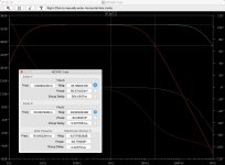
Nice job with the battery adaptation, but why did you add C5/C12 (22nF) at the output? It creates a severe high frequency filter, -6.5dB @ 20KHz.... Some changes have been made to the parameters of the capacitor, which seems to be better.
If your intent was to reduce bandwidth, 22nF is excessive, eg: Red trace is with 22nF, Green trace is with 220p.

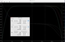
OTOH, C5/C12 are redundant. The same can be achieved simply by changing the value of C4/C10. Here are 3 values for C4/C10: 220p, 500p and 1nF.

Similar in that both are battery operated common-base, otherwise different topology.Nice work. It's an interesting circuit, similar to the WM Leach design that was published in Audio as a DIY project way back. (Any oldsters remember that?)
I do remember the Leach, have built 2: a crude one way back in '88, another more recently (2018) and properly: The Leach moving coil pre-preamp
https://audiokarma.org/forums/index...g-coil-pre-preamp.838004/page-5#post-12415488
It's a simple and very effective design, still holds its own against the rest today.
P1, the power and bypass switch, looks like an integrated circuit with six j-Fets in your schematic.
I am sure the operation is better without this switch working on the input signal.
I am sure the operation is better without this switch working on the input signal.
You can throw out the large coupling caps and directly servo out the input offset - I did this on my X-Altra MC/MM to allow direct coupling of the MC cart. The common base configuration gives the lowest noise for MC inputs - Leach was way ahead of everybody else with this configuration. The X-Altra MC/MM achieves 232 pV rt/Hz input referred noise (measured).
?You only moved the coupling caps to the output, they are still required.
The input z on both these designs is very low - close to about 1.5 Ohms on the X-Altra MC/MM. Removing the input caps offers real benefits wrt noise and response. I don’t have a problem with the output caps.
感谢你做技术验证,22NF消减了高频,原始的MCA10在输入和输出的RCA连接器上都并联了22NF的电容器。这也是重建它的原因之一,重建的PCB适合任意修改,我附上一些原始的图片。Nice job with the battery adaptation, but why did you add C5/C12 (22nF) at the output? It creates a severe high frequency filter, -6.5dB @ 20KHz.
If your intent was to reduce bandwidth, 22nF is excessive, eg: Red trace is with 22nF, Green trace is with 220p.
View attachment 1329102
OTOH, C5/C12 are redundant. The same can be achieved simply by changing the value of C4/C10. Here are 3 values for C4/C10: 220p, 500p and 1nF.
View attachment 1329103
- Home
- Source & Line
- Analogue Source
- Ortofon MCA10 Moving Coil pre amplifier clone