The crossover for Dennis Murphy’s CAOW1 2-way speaker design calls for a 0.06 mH inductor with a 0.10 ohm DCR. In his write-up Dennis indicates “You will probably have to order a 0.10 mH inductor and unwind a little less than half of the wire. The value is not critical.”
Dennis Murphy's CAOW1
Dennis is correct so I have some questions about how to arrive at 0.06mH from a 0.10mH inductor, or at least close enough to work:
1. Can I weigh the coil on a digital scale then unwind and remove material bit-by-bit until the coil weighs 60% of the original value? The only thing I would be measuring here is weight of the coil.
2. Would it be better to purchase an LCR meter to measure inductance as I unwind, or is this overkill considering Dennis’ saying the value is not critical?
3. In general, do most people verify the accuracy of other crossover components or trust the manufacturer’s values? If most verify other components I may get an LCR meter to check resistors and capacitors in addition to getting really close with the inductor.
Peak LCR Meter
Thanks in advance for your advice!
Attachments

The weight is not going to be reliable, and you should unwind ~25% of the turns, not half, but measurement is the most accurate option. For a one-off, a dedicated meter is not required: if you have some basic instruments, the value can be measured accurately enough, with the resonance method for example. On the www, you can find a number of improvised techniques suited to your case
The issue is that inner turns are shorter than outer ones. If you remove only outers, the weight will not be proportional to turns. If you remove inners, the bigger internal coil diammeter will make the inductance higher than expected.
So if only you need an approximation, remove part from outer turns and part of inner ones if possible. But always the measurement will be better.
So if only you need an approximation, remove part from outer turns and part of inner ones if possible. But always the measurement will be better.
If it's not "too many" turns to do the following, unwind the whole inductor while counting the total turns. The turns ratio is proportional to the square root of the inductance ratio. 0.06 / 0.1 = 0.6. the square root of 0.6 is 0.77. If the original was 120 turns, you would wind back 120 * 0.77 = 92 turns.
An LCR meter would likely be overkill for this one thing, but if you're going to make more crossovers for multiway speakers, it'll be a good investment.
An LCR meter would likely be overkill for this one thing, but if you're going to make more crossovers for multiway speakers, it'll be a good investment.
+ 1 on noticing that Inductance is directly proportional to turns squared
So removing "less than half" is not the right way.
Also: unless designer clearly states total number of turns (guess he does not), how do you know what amount to remove?
You definitely need a meter, so you can unwind, say, 10 turns, remeasure, now you have a rough idea on how many need removing.
Plus a final recheck.
Now if he specifically said: "remove 27 turns" or whatever, that's different.
There is a very inexpensive LCR meter (which also is a semiconductor device tester) sold on eBay for USD 13 without case. It is called Mega328 LCR meter and you can find many dozens of sellers on the eBay website. Survey the landscape carefully, looking for best price, shortest shipping time, and lowest shipping cost.
They all copied the original Mega328 firmware written by Karl-Heinz Ku:bbeler for his original thesis project. Lucky for us, his thesis is available on the web: "TransistorTester with AVR microcontroller" and I am sure that bing.com or duckduckgo.com can find it easily.
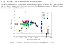
Here is a graph from that thesis. It shows that the error between Mega328-reported inductance, and actual correct inductance, is approximately 10 percent for a 60 microhenry inductor. If you need better accuracy than that, spend more money and purchase a grown up instrument like a DER-EE DE-5000 LCR meter from Amazon (most expensive option) or eBay (least expensive option)
_
They all copied the original Mega328 firmware written by Karl-Heinz Ku:bbeler for his original thesis project. Lucky for us, his thesis is available on the web: "TransistorTester with AVR microcontroller" and I am sure that bing.com or duckduckgo.com can find it easily.
Here is a graph from that thesis. It shows that the error between Mega328-reported inductance, and actual correct inductance, is approximately 10 percent for a 60 microhenry inductor. If you need better accuracy than that, spend more money and purchase a grown up instrument like a DER-EE DE-5000 LCR meter from Amazon (most expensive option) or eBay (least expensive option)
_
Attachments
Thank you for all the replies. Another alternative I just thought of it to contact an inductor manufacturer (Solen or US Coils) to see if they could provide the value I need even though it is a non-catalog item. I'll do that and post their replies.
At least a few years ago Madisound could provide non-standard inductor values for a small upcharge, iirc it was just 10% over the next standard value or so.
Also Jantzen does have 0.06m air-core coils, don't know if they have a US distributor.
Edit: apparently they do (see here), it may be special order though.
Also Jantzen does have 0.06m air-core coils, don't know if they have a US distributor.
Edit: apparently they do (see here), it may be special order though.
Madisound has a 0.05 mH / 0.17 DCR inductor HERE. I wondered how much of a difference it would make in the response. So I converted the OW1 frequency response and impedance graphs (LINK) into .frd and .zma files respectively. I then created a XSim project with the original inductor and then the Madisound inductor. Here's the modified Xover and response plot of both Xovers. The red plot is the original Xover and the blue plot is the modified Xover.

 vs Modified (Blue) Response.jpg")
- Home
- Loudspeakers
- Multi-Way
- Seeking Advice for Unwinding an Inductor