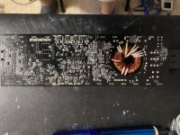
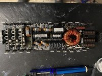
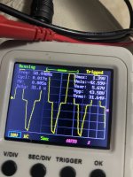
Hi I have a Rockford T1000.5. I has no output, it powers up but makes a buzzing noise and all the clip lights are flashing. I checked all the fets and no issues. I found a 1uf capacitor with a hole blown in it. I removed it from the circuit and I’m waiting for replacement to arrive. I checked the square wave on the ps fet and it start off fine for two seconds then it turns to the monstrosity in the photos. Im thinking there is an issue with the drive IC. Thoughts?
Attachments
That looks like the waveform from a power supply that's regulated. Reduce the 12v supply voltage and it will likely become more like you expect.
Are the regulated power supplies producing the correct voltages?
Are the regulated power supplies producing the correct voltages?
I measured at the rectifiers +/- 34 volts. I measured the voltage regulators and one was at -21 and the other was +7. I’m not sure where to measure the regulated power supplies.
What makes up this amp? Four 2092 or other driver ICs and one BD type amp for the 5th channel?
Did you use the same reference point when measuring rail and regulated voltage?
What is the DCV on the power supply pins of the op-amps near the RCA input section of the amp?
Did you use the same reference point when measuring rail and regulated voltage?
What is the DCV on the power supply pins of the op-amps near the RCA input section of the amp?
Yes it has four 2092 drivers.
Pretty sure it’s a bd amp for the sub channel
I used the same reference point when I measured the voltages.(amp ground)
I found two TL072 op amps near the rca input section. The power supply pins read 6.4 volts.
On a side note the screeching noise is coming from the power supply transformer.
Pretty sure it’s a bd amp for the sub channel
I used the same reference point when I measured the voltages.(amp ground)
I found two TL072 op amps near the rca input section. The power supply pins read 6.4 volts.
On a side note the screeching noise is coming from the power supply transformer.
The TL072 generally has a positive and a negative supply. Are both of the supply pins +6.4v?
Did you try reducing the 12v supply voltage to see if the waveform cleaned up?
What's the driver IC for the power supply? A boost/flyback will have a different waveform than a push-pull.
Did you try reducing the 12v supply voltage to see if the waveform cleaned up?
What's the driver IC for the power supply? A boost/flyback will have a different waveform than a push-pull.
Lower the 12v supply until the amp shuts down. Then go up slightly and power up.
Check the waveform on the drain of the PS FET.
Can you tell which regulators are producing the TL072 supply voltage?
Check the waveform on the drain of the PS FET.
Can you tell which regulators are producing the TL072 supply voltage?
I lowered the voltage until it turned off. I turned up the voltage it came back on around 10 volts. It had a squarish waveform and no noise for a second. As soon as the waveform changed the transformer started screeching.
Attachments
I think you should wait until you get the capacitor replaced to do anything more.
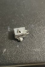
What part of the circuit did it come out of?
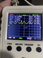
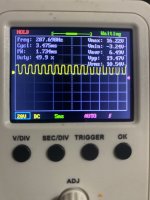
If you set the scope to 5v/div and 10us, does the frequency read lower (when it's a square wave)?
What part of the circuit did it come out of?
If you set the scope to 5v/div and 10us, does the frequency read lower (when it's a square wave)?
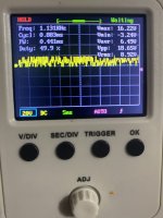
Set it to 5v and 10us. The frequency is 30 when it’s a square wave.
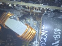
I’m not sure what part of the circuit it came from. The components are absolutely crammed on this board. It was between a vertical board and an inductor.
I’ll have the capacitor in a few days I’ll install it and let you know how it goes. I appreciate the help as always.
I’m not sure what part of the circuit it came from. The components are absolutely crammed on this board. It was between a vertical board and an inductor.
I’ll have the capacitor in a few days I’ll install it and let you know how it goes. I appreciate the help as always.
Attachments
30k is much better.
It's likely part of the output filter, possibly connected across the subwoofer speaker terminals.
If that's how it'a being used, the output filter inductor may be intermittently shorted. If the cap is being used in that way and it blows again, you will need to find where it's shorted or rewind it with new wire.
Hi I wanted to give an update. I soldered in the new capacitor, square wave looks good and no clip lights. I checked the inductor and it looks normal, fingers crossed. I’m going to put it back in the heat sink for further testing. Thanks again!
After it's back in the sink, FETs clamped, twist/push/pull on that inductor, watching the current draw to see if the current draw changes when moving the inductor.
I clamped everything back in and moved the inductor and no fluctuations. I did make a mistake with the thermal pads, I cleaned them and applied new thermal paste. I was not aware that Rockford uses thermal pads that are conductive on one side. I installed them backwards by mistake. Took me an hour of head scratching before I figured it out. Everything is working good now.
- Home
- General Interest
- Car Audio
- Rockford T1000.5